background image

Maintenance overview Maestro CV

Maintenance location

Work instructions

Interval

After 10 operating hours

Retighten all screw and plug-in 

connections as well as the hydraulic 

connections. 

Even  firmly  tightened  screw  connections  can  come  loose 

(e.g. because of material settlement or paint residues between 

the screw elements). This can lead to loose screw connections 

and leaking hydraulic connections.

once

Retighten all wheel nuts
M18 x 1.5 - 300 Nm

M22 x 1.5 - 510 Nm


¾

initially after 10 hours or 50 km 


¾

again after 10 hours or 50 km 


¾

then retighten daily until the screws have settled and further tightening 

is no longer possible


¾

then always before the start of the season and every 50 operating hours

Retighten all screws on the clamping 

plates of the drill units, see section 

Clamping plates

 (torque 180 Nm)


¾

for the first time after 10 hours


¾

once more after 50 hours

Before the season

Complete machine

Read the operating instructions carefully as a refresher.

Check all screw connections for firm seating and retighten as necessary

Check condition and function of all protective features and replace, 

if necessary
Check electrical lines for damage and replace, if necessary.

In use
Hydraulics


WARNING

Lower all hydraulically lifted parts (e.g. wings, packer, undercarriage, 

etc.) to the ground before performing any work on the hydraulic system. 

Depressurise the hydraulics on the tractor and implement side! Empty 

the pressure accumulators.
Risk of scalding! Allow hydraulic oil and hydraulic components heated 

during operation to cool down before any work on the hydraulic system.
Observe the notes on hydraulics in the chapter 

Safety and responsibility

.

Hydraulic system and components

Check all hydraulic components and hoses for function, 

leak tightness, fastening and chafing

40 h

Hydraulic hoses

Check the hydraulic hoses regularly for damage (cracks, chafing, etc.).

Replace damaged and faulty hoses immediately.
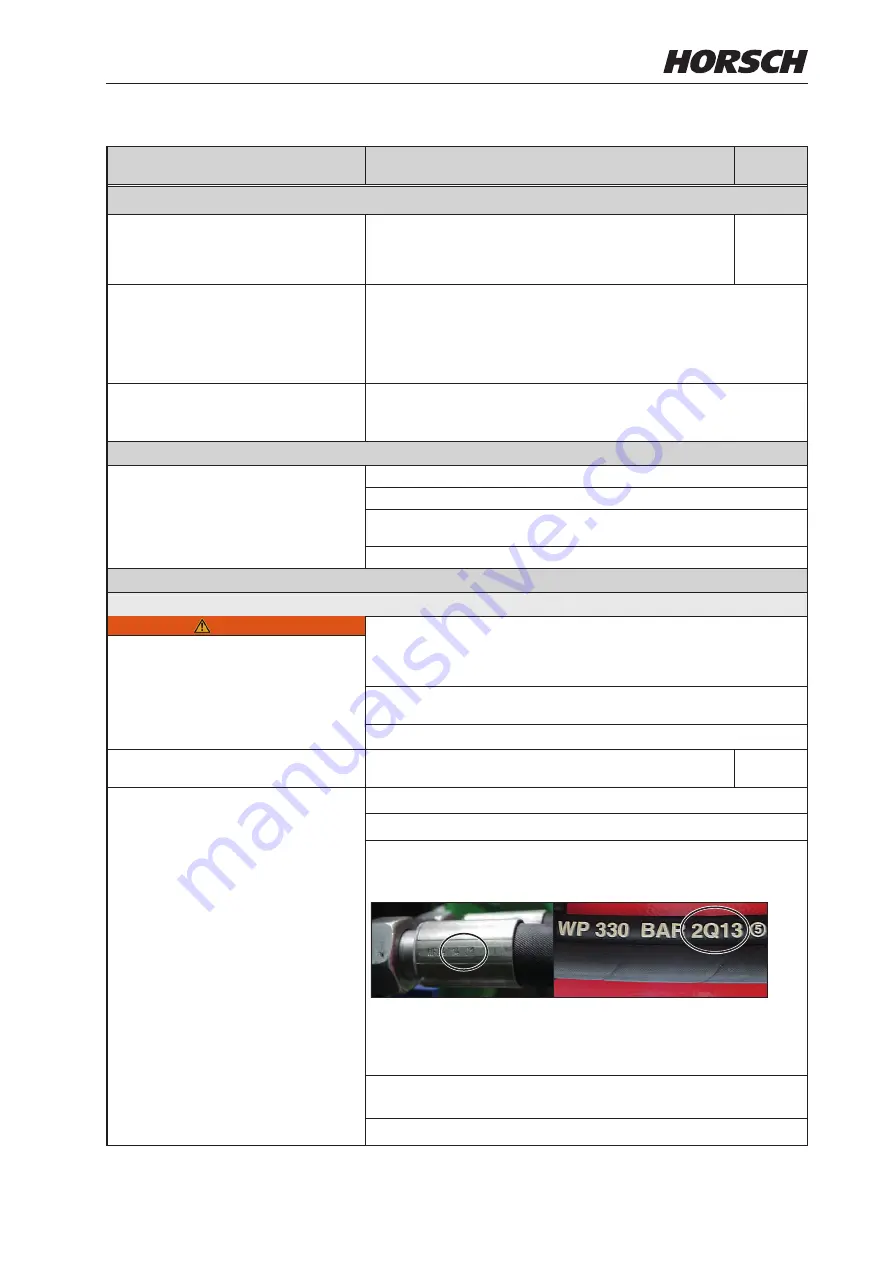
Hydraulic hoses must be replaced after 6 years. Pay attention to the 

manufacturing date on the crimp sleeve (year/month) and the hose 

(quarter/year):

Crimp sleeve

Hose

Depending on the conditions of use (e.g. weather influences) or in case 

of higher strains on the machine the hoses may need to be replaced 

earlier.
Have the hydraulic system checked by an expert at least once every 

year.

Follow the country-specific regulations and directives.

127

Summary of Contents for Maestro 12.45 CV

Page 1: ...TRANSLATION OF THE ORIGINAL OPERATING INSTRUCTIONS READ CAREFULLY PRIOR TO STARTING UP KEEP OPERATING INSTRUCTIONS IN A SAFE PLACE ART ISSUE OPERATING INSTRUCTIONS 0236 12 2019 8043 Maestro CV...

Page 2: ......

Page 3: ...9431 7143 9200 E mail info horsch com Customer No HORSCH Confirmation of receipt of machinery Warranty claims become only effective when the first use of the machine is reported to HORSCH Maschinen Gm...

Page 4: ...pp Horsch Hubertus Bultmann Gesch ftsf hrer Leiter Forschung und Entwicklung S maschine Maestro 8 CV Maestro 9 CV Maestro 12 CV Translation of EC Declaration of Conformity Directive 2006 42 EC The man...

Page 5: ......

Page 6: ...Marking of hydraulic hoses 34 Aluminium clips 35 Lighting 36 Instruction stickers 37 Operation 41 Connecting Parking 41 Connecting 41 Transport position 42 Parking 44 Anti theft devices 45 Wings 46 Un...

Page 7: ...ance of metering unit 106 Troubleshooting 107 Optional equipment 109 Brake system 109 Pneumatic brake 109 Brake valve unit 109 Hydraulic brake 113 Micro granulate facility 115 Adjustment and operation...

Page 8: ...d proper acceptance of the machine The warranty period starts with the date of delivery We reserve the right to alter illustrations as well as technical data and weights contained in these operating i...

Page 9: ...manufactured by HORSCH with greatest care However despite the intended use deviations in placing quantity up to total failure may be caused by e g damage caused by external influences wear of wear it...

Page 10: ...law must also be complied with Any other kind of use of the machine contradict ing the above especially connecting attachment to an agricultural trac tor that is not suitable using the machine as a m...

Page 11: ...r with the safe opera tion of the vehicle The person knows all applicable road traffic regulations and is in possession of a valid driving permit for road travel A person being instructed must only wo...

Page 12: ...jewellery Safety in traffic DANGER No passengers are allowed to ride on the machine Pay attention to the permissible transport widths and heights Pay attention to the trans port height when passing u...

Page 13: ...essary Check tyre pressure regularly Damage to the machine Damage to the machine can impair the op erational safety of the machine and cause ac cidents This can lead to severe or even fatal physical i...

Page 14: ...and screwed con nections regularly for leaks and any visible external damage Use only appropriate means when searching for leaks Repair any damage immediately Oil sprays can cause injuries and fire P...

Page 15: ...ds to be switched off If persons need to leave the cabin despite the voltage flashover e g in case of a potential life threatening risk of fire Jump away from the machine Ensure a safe stand when jump...

Page 16: ...with the machine lowered The components have only been designed for forward travel in the field and may be damaged when reversing Changing equipment wear items Only pulling tools may be attached that...

Page 17: ...his type approval needs to be renewed Care and maintenance Inappropriate care and maintenance put the operational safety of the machine at risk This can lead to accidents with severe or even fatal phy...

Page 18: ...ths to cure and could thus be damaged if this time has not yet expired All other maintenance and repair tasks which are not described in the operating instructions must only be carried out by an autho...

Page 19: ...ticed Failing to pay attention to the danger zone can result in severe or even fatal physical injuries Do not stand under lifted loads Lower such loads to the ground first Instruct persons to leave th...

Page 20: ...4 Before commissioning the machine you need to read and follow the operating in structions 00380055 Caution for fluids spraying out under high pressure follow the notes in the operating instruc tions...

Page 21: ...e to the slewing range of the machine 00381117 The pressure accumulator is charged with gas or oil pressure Dismantle and repair only in strict compliance with the instruc tions in the technical manua...

Page 22: ...Positions of safety stickers depending on equipment Safety stickers with the addition 2x can be found on either side of the machine 2x 00386221 Filling auger Agitator shaft 18...

Page 23: ...rt Depending on country specific regulations and working width the equipment can be transported on public roads either attached to a tractor or on a trailer or low loader The permissible dimensions an...

Page 24: ...dapting the seed bar The incline of the seed bar depends on the con necting height of the machine on the tractor It must therefore be adapted accordingly see chapter Operation Adapting the seed bar 20...

Page 25: ...5 9 Dropping height seed cm 45 45 45 Working speed km h 2 12 2 12 2 12 Tyres Load index Air pressure bar Permissible load bearing capacity at 40 km h kg 270 95 R 36 139 A8 4 2 430 500 85 R 24 177 A8 2...

Page 26: ...axles 1 2 3 Type plate The type plate with the CE marking is located on the frame of the machine Data on the type plate Information on year of manufacture Year of manufacture in VIN Vehicle Identific...

Page 27: ...Maestro 8 CV 5470 665 3900 6500 3000 5900 8 70 CV 6360 8 75 CV 6570 8 80 CV 6790 23...

Page 28: ...5470 6500 3900 615 3000 Maestro 9 CV 6700 9 70 CV 7590 9 75 CV 7160 9 80 CV 7590 24...

Page 29: ...Maestro 12 CV 5550 6500 665 3900 3000 6790 5900 25...

Page 30: ...be able to use the machine as intended Implement attachment Maestro 8 X CV 9 X CV 12 45 CV 12 50 CV Adjustable drawbar circular drawbar eye with ball and socket joint bolt 32 mm bolt 42 mm bolt 32 mm...

Page 31: ...drive Oil quantity hydraulic fan fertiliser 28 l not with PTO shaft drive Double acting control units 1 hydraulic functions 1 hydraulic fan direct drive fertiliser with adjustable flow rate 1 hydrauli...

Page 32: ...der 10 Drill unit 11 Fertiliser distributor tower 12 Seed hopper 13 Fertiliser hopper 14 Railing steps 15 Hoses 1 2 4 3 5 7 8 9 10 11 12 13 14 15 6 WARNING Danger of injury Do not look into the near a...

Page 33: ...e been de pressurized on both machine and equipment sides NOTE Operate the machine with mineral based hydraulic oil Do not mix mineral oils with organic or ester oils The hydraulic circulation of the...

Page 34: ...r 12 Double acting lock valve 13 Hydraulic cylinders wings 14 Hydraulic cylinders bout marker T T T 10 1 10 2 20 1 20 2 20 3 20 4 40 30 110 60 70 70 50 2 50 3 50 4 50 5 V5 S S H H DS DS HZ HZ SZ SZ HK...

Page 35: ...t cooler 2 Return filter 3 Hopper venting filter 4 Suction filter 5 PTO shaft fan pump 6 Valve block 7 Vacuum fan motor 8 Fertiliser fan motor a coulter pressure connection b coulter pressure connecti...

Page 36: ...A 5 5 a 1 2 3 4 5 7 6 8 6 b c P T A 1 Shuttle valve 2 Pressure gauge coulter pressure 3 Valve block 4 Check valve 5 Check valve restrictor 6 Separating point 7 Ball valve field road 8 Coulter pressur...

Page 37: ...Filling auger 1 Hydraulic coupling tractor auger 2 Flow control valve 60 l min 3 Check valve 4 Three way rotary spool valve 5 Hydraulic motor 160 cm 1 2 3 4 5 33...

Page 38: ...pective hoses Hydraulic valve block Fan fertiliser Fan vacuum Pressureless return The return flow pressure of the leak oil line must not exceed 5 bar Auger Hydraulic brake NOTE The following hydraulic...

Page 39: ...s Limbs may be pinched or crushed by uninten tional retraction of the piston rods When attaching or removing the clips the machine must be parked with the parking brake pulled During this time nobody...

Page 40: ...No Desig Colour Function 1 L yellow Blinker left 2 54 g 3 31 white Earth 4 R green Blinker right 5 58 R brown Rear light right 6 54 red Brake light 7 58 L black Rear light left WARNING Traffic accide...

Page 41: ...see Maintenance overview Tyre pressure 4 0 bar Check the tyre pressure at regular inter vals adapt if necessary see maintenance overview Always plug in all hydraulic lines Otherwise components could...

Page 42: ...ighten with the appropriate torque Retighten the wheel nuts wheel bolts after 50 km or 10 hours Retighten every day see maintenance overview Ensure leak tightness of seed hopper and the entire pneumat...

Page 43: ...5 9 Achslast Axle load Charge Essieu min kg max Ausgangsdruck Output pressure Pression de sortie bar beladen loaded charg leer emtpy vid Eingangsdruck Input pressure Pression d entr e bar 6 5 WABCO 4...

Page 44: ...Lashing points Hook fastening gear lashing belts chains etc here 00385757 60010418 Jack lifting point area where the jack must be attached for the wheel change 00385757 40...

Page 45: ...machine Connecting The machine must be properly connected to a tractor before any machine movements DANGER Serious accidents from loss of stability Machines with pneumatic brake system Do not move th...

Page 46: ...machine or machine parts Before driving off Clean all thrown up soil off the entire machine Check function of lighting system Lock the control units mechanically or electri cally depending on the vers...

Page 47: ...Position of control units during road travel Position Control unit Floating position Locked position Supply Hydraulic valve block Fertiliser fan Vacuum fan Auger 43...

Page 48: ...d Maintenance Park the drill in a shed or under a roof so that no moisture can accumulate in hopper metering unit and seed pipes Parking the machine folded 1 Fold the machine see Folding 2 Position th...

Page 49: ...chine Machines with drawbar eye Position the drawbar by cranking on the support to be able to release the bolt Release the bolt and move the machine to clear Machines with ball and socket coupling Rel...

Page 50: ...t has been fully connected The machine must not be in an inclined posi tion when folding it Fold the machine only on a level and firm surface Fold the machine only at standstill CAUTION Damages to the...

Page 51: ...Switch on the hydraulic Lift function in the display 8 Continue retracting the hydraulic cylinders for lifting lowering thereby lowering the seed bar to the ground 2 1 9 The bout markers are folded hy...

Page 52: ...by lowering the seed bar onto the transport hooks on the hopper 10 Switch off the machine control 11 Switch the control units to the locked position CAUTION Damages to the machine Fully fold the wings...

Page 53: ...rtiliser would remain in the hoses and cause blockage Without optional auxiliary equipment the fertiliser hoses are not monitored by the drill controls Working speed The working speed depends on the f...

Page 54: ...ed position Supply Hydraulic valve block Fertiliser fan Vacuum fan Auger Position of control units during use in the field Working speed Reduce the working speed in case of unsteady run of the drill u...

Page 55: ...ltivation tools and optional equip ment still in a serviceable state Are all cultivation tools adjusted correctly Pneumatic system Hydraulics Check the pressures on the pressure gauges on the seed hop...

Page 56: ...fertiliser hopper in drilling position Use a spirit level if necessary 2 Aligning the seed bar By adjusting the seed bar the parallelograms of the drill units are aligned horizontally position during...

Page 57: ...loves for cleaning and maintenance work CAUTION Damages to the fan motor Connect the leak oil line to the leak oil port of the tractor Note the return flow pressure of max 5 bar in the leak oil line A...

Page 58: ...anular compound 7 Fan vacuum 8 Vacuum measuring point 9 Pressure gauge for coulter pressure supply 10 Pressure gauge for vacuum Variant with seed container Overview NOTE The scales on the throttle val...

Page 59: ...ng point 7 Seed supply 8 Micro granular compound metering auger 9 Distributor tower for micro granular compound 10 Fan vacuum 11 Vacuum measuring point 12 Pressure gauge for coulter pressure supply 13...

Page 60: ...tem must be absolutely leak tight Leaks will cause sowing faults 1 2 1 Vacuum fan with hydraulic motor 2 Exhaust air hose Maintenance WARNING Hazard from harmful dust fertiliser dressing on all compon...

Page 61: ...he pump or the gear could get damaged Observe the maximum rotary speed of 800 rpm to prevent damage to the gearbox Fan fertiliser WARNING Risk of injury from running fan Never operate the fan without...

Page 62: ...ow is guided through the cooler and a filter back into the oil tank NOTE Allow the PTO shaft pumps to warm up prior to use in the field for approx 5 min at idle speed Fan speed adjustment The rotation...

Page 63: ...e oil if necessary Retighten the clamping tapers on the fan shafts see chapter Fan Flange NOTE The radiator fins must be cleaned at regular in tervals as otherwise the cooling and fan air flow will be...

Page 64: ...acement The guide values must only be fallen short of if the correct distribution at a lower speed was determined during measurement of the trans verse distribution Fan speed too low If the fan speed...

Page 65: ...iator fins are soiled and cause clogging of the fertiliser hoses Clean the radiator fins at regular intervals Retightening the fan flange The clamping taper fixates the fan wheel and additionally clam...

Page 66: ...ooler dirty PTO shaft speed too high Reduce power and check oil level Check pressure on fan Change oil and oil filter Clean protective fan grid Clean radiator fins Avoid unnecessary cooling power redu...

Page 67: ...s to the metering units 8 Maintenance flaps residual quantity emptying Adjusting the air flow The required air flow depends on the travel speed and other influences The specified values therefore need...

Page 68: ...always be set in connection with the required fan speed for fertiliser With high speeds adjust the valve rather to wards 0 for a high fertiliser quantity With low fan speeds adjust the valve rather to...

Page 69: ...ng Seed jammed at the mainte nance flaps causes leaks Air losses in the area of the central distributor may cause serious drilling errors Error messages in the drill controls may be caused by air loss...

Page 70: ...errors and unnecessary wear inside the metering unit Always keep the covering closed with the elastic to protect the fertiliser against con tamination dust and moisture NOTE During transport travel e...

Page 71: ...ributors for solid fertiliser and micro granular compound optional equipment are mounted to the rear of the frame above the seed bar They distribute fertiliser and granulate through the hoses to the c...

Page 72: ...sses the coulter discs into the ground until the depth guide rollers rest on the ground Hydraulic coulter pressure The hydraulic cylinders for the coulter pressure transfer additional pressure on the...

Page 73: ...y the following values Item 2 springs 4 springs 1 10 kg 20 kg 2 23 kg 46 kg 3 30 kg 60 kg 4 45 kg 90 kg Direction of travel 1 3 2 4 Positions 1 4 Lift the machine Pull the bolt out of the spring holde...

Page 74: ...g on larger areas also regularly in between The individual drill units of the Maestro are flanged to a foldable transverse frame All assembly groups for single grain drilling are attached to the drill...

Page 75: ...in the event of moist or comparatively small seed if necessary Open all seed hoppers and fill them uniformly Close the seed hopper and secure them with the snap locks Maintenance The plastic parts of...

Page 76: ...r work without clearing unit The clearing unit or support skid have the fol lowing functions Scraping the insides of the coulter discs Protection of the downpipe from damages a b a coulter discs b cle...

Page 77: ...king 1 on the matching parts Coulter disc Trap roller Clearing unit support skid Adjust the position of the trap rollers if the coulter discs are worn Coulter disc diameter 15 381 mm 370 mm 350 mm 330...

Page 78: ...Depth setting scale Depth guide wheels During drilling the depth guide rollers must touch and clean the coulter discs The position of the wheels to the coulter discs must be adapted e g when readjusti...

Page 79: ...ll units behind the tractor tracks a greater drilling depth may need to be set on these drill units Regularly check wear and drilling depth on the drill units behind the tractor tracks Trap rollers On...

Page 80: ...cs Press rollers With their V shaped arrangement the press rollers close the seed channel and press the soil against the seed With the adjustment lever the consolidation ef fect of the press rollers c...

Page 81: ...beet and sorghum small seed c spacer bushing Always adjust the same gap width on all press rollers Loosen the screw take off press roller and spacer bushing c Assemble spacer bushing and press roller...

Page 82: ...ess wheel in combi nation with the rubber press roller to limit the submersion depth Spike press wheel Displacing the axle In case of blockage caused by stones or harvest residues one of the two press...

Page 83: ...Attach the rubber press roller 3 offset to the rear toward the finger or spike press wheel Mount the finger press wheel in the correct position The fingers must be directed toward the rear in the dire...

Page 84: ...pth WARNING Machine parts can cause severe crushing injuries etc Secure the machine against rolling lift it and support it with proper jacks Do not work under the raised machine without proper safegua...

Page 85: ...the inside and the lower bolt 2 to the outside 1 2 Limit toward the bottom soft soil conditions Align and insert the adjustment bolt so that the upper bolt 1 points to the outside and the lower bolt...

Page 86: ...ll units of the equipment variant with central hopper supply are equipped with a hose for the seed supply instead of the seed hopper Components Motor motor control 2 1 4 3 5 6 7 8 Row Module Planter R...

Page 87: ...g disc 6 which transports them further The separator 7 scrapes off the excess grains There is one grain each in each hole of the metering disc At the grain dispenser 9 the grains are sepa rated from t...

Page 88: ...isc or the vacuum level Check setting Sow for a length of approx 50 m before each check Switch off the fan and remove the removable half of the housing Check filling of the metering disc and adjust th...

Page 89: ...it scraper For certain types of fruit a scraper must be in stalled to separate the grains from the metering disc always at the same location Variants Execution Area of application B Sugar beet C Rape...

Page 90: ...s the down pipe on the drill unit Spigot hooked up Guide the downpipe down at the front edge of the recess in the drill unit 2 3 Plug in the top locking bolt and secure it with a cotter pin 2 Route th...

Page 91: ...ks up slowly It starts with a deposit behind the peak until it is com pletely blocked Downpipe with blockage developing NOTE The sensor is unable to detect faults in the bot tom range of the downpipe...

Page 92: ...crewdrivers Do not damage the cables When assembling housing parts join the individual parts correctly applying only slight pressure Changing and adjusting components Various quick change fixtures on...

Page 93: ...t inserted the metering disc will be pressed against the housing during use and lock up As a result no seed is placed or the seed quan tity and placement is undefined To resolve the blockage refer to...

Page 94: ...nit settings table Ejection wheel Colour Number of teeth blue 5 yellow 7 red 10 green 11 white 20 Push on the ejection wheel when changing it so that the side shown points toward the outside Separator...

Page 95: ...ment 6 Check the scraper for axial mobility on the screws clean if necessary 7 For disassembly squeeze the catch 1 to gether and pull out the scraper Remove the inspection flap and mounting plate Clea...

Page 96: ...disc and housing and reduce if neces sary see Changing components 3 4 Removable housing half vacuum side 6 Carefully clean the downpipe from the top and bottom with the cleaning brush provided 5 Do n...

Page 97: ...tering disc with the next smaller or next larger hole diameter and run the test again Select the metering disc that produces the best singulation quality and install it in all metering units 2 Vacuum...

Page 98: ...ly seated Does the metering disc match the seed and has the E Manager been set accordingly Have separator and push out wheels been correctly selected and installed Has the grain feed gate been set cor...

Page 99: ...5 6 25 to 40 5 01244181 CORN 1 0 1 row of holes 01240800 Maize 19 x 5 0 mm 01244150 5 6 25 to 40 5 01244181 CORN 1 0 1 row of holes 01240800 Maize 19 x 6 0 mm 01244160 5 6 25 to 40 5 01244181 CORN 1...

Page 100: ...242630 2 3 30 to 65 10 01242681 CORN 1 0 1 row of holes 01240800 Soybeans 48 x 4 0 mm 01242640 3 4 30 to 65 10 01242681 CORN 1 0 1 row of holes 01240800 Soybeans 96 x 3 0 mm 01242503 2 3 30 to 65 20 0...

Page 101: ...ts would have to be emptied again All rows on which no testing is performed Set the grain feed gate to the 0 position The seed must be dry and as far as possible free of dust and foreign objects The s...

Page 102: ...so open and check the rows behind the tractor tracks Uncover the grains carefully from the side so that they will not be displaced in the seed bed Measure the placement depth and the grain spacing The...

Page 103: ...Metering disc jammed If the cotter pin on the rotary handle has been shorn off or is missing the metering disc is pushed against the housing and will jam against it Access the function for clearing o...

Page 104: ...g the coulter pressure NOTE Set a low pressure first and increase it as necessary The coulter pressure for fertiliser placement can be adjusted by two different springs in different positions The asso...

Page 105: ...depth 50 70 90 mm 1 2 50 mm 70 mm 90 mm Loosen the screw 1 Unscrew the screw 2 far enough so that it can be moved in the hole pattern Choose the desired position and tighten the screws 2 Tighten the s...

Page 106: ...lter discs as possible However they should not rest too firmly against the coulter discs Inspection It must be possible to turn the depth guide roller by hand against the coulter disc 1 2 Loosen the l...

Page 107: ...nly a few individual parts and can be dismantled without tools 1 2 3 4 5 6 7 Metering unit 1 Housing 2 Drive motor 3 Clearing valve with sealing lip 4 Rotor 5 Side cover with rotor bearing 6 Side cove...

Page 108: ...the side cover Pull out the rotor with the drive shaft Fertiliser residues may be present below the gate valve when the hopper is full Remove the fertiliser inside the metering unit prior to installa...

Page 109: ...p any more and tighten it Assemble the side cover check the setting once again and reinstall the rotor Metering unit with Venturi type injector The Maestro machines are equipped with a Venturi type in...

Page 110: ...season The bearings in the side cover in particular can be damaged or may become hard moving be cause of dressing dust If necessary keep bearings in stock and replace in due time 2 1 2 Drive motor 1 S...

Page 111: ...scraper Air supply grille soiled Clean air supply grille Grain sensor dirty Clean downpipe with the supplied brush Grain geometry misshapen or inhomogeneous Reduce working speed Increase the vacuum U...

Page 112: ...leaning Motor defective Replace fuses Replace motor workshop work Downpipes or drill discs clogged Drill has been lowered and rolled backwards Move the drill only forward when lowered Support skid ins...

Page 113: ...on hopper empty 5 Service brake release button 6 Parking brake button 7 Test port Optional equipment Brake system The machine can be equipped with a pneumat ic or hydraulic brake system The machine is...

Page 114: ...druck Output pressure Pression de sortie bar A 1 6 300 3 800 A 1 6 700 4 3 4 500 4 100 4 100 3 2 A 1 7 800 5 400 4 900 A 1 8 400 5 400 A 1 9 000 6 400 5 900 5 900 3 4 4 1 4 4 4 8 4 6 5 3 5 6 5 9 Achsl...

Page 115: ...the threaded rod with nut and washer from the brake cylinder and fasten it in the parking position Maintenance Drain the air vessel every day during oper ation Air vessel with drain valves Clean the f...

Page 116: ...Check Pull the brake lever by hand The pis ton rod must move approx 7 20 mm toward the outside depending on the axle and length of the lever 2 2 112...

Page 117: ...the tractor 4 Press the brake pedal on the tractor all the way down for approx 5 s to fill the spring accumulator Hydraulic brake The hydraulic line controls the brake power to the brake cylinders WAR...

Page 118: ...t rests against the screw head Maintenance Adjust the brake lever every 6 months see section Pneumatic brake Maintenance WARNING The cable may be caught by other machine parts and thus trigger flat ou...

Page 119: ...empty sensor 7 Differential pressure sensor 8 Calibration switch Adjustment and operation Depending on the granulate quantity the me tering unit can be fitted with different augers The actual displace...

Page 120: ...placed and the calibration process repeated Seed calibration The calibration sequence and the input on the terminal are identical with the calibration of the fertiliser metering unit see E Manager in...

Page 121: ...6 km h 8 km h 10 km h 12 km h 14 km h 80 75 70 65 60 55 50 45 40 35 30 25 20 15 10 5 kg ha Metering auger 66 cm 117...

Page 122: ...itial use The metering units must first run in during initial use NOTE During initial use repeat calibration after one hour running In use During drilling the required amount of air is taken from the...

Page 123: ...granulate facility must therefore be checked and cleaned before use and several times during use for leak tightness and deposits Granulate placement In the standard design granulate is placed be twee...

Page 124: ...Make sure before reactivation that no persons are present in the danger zone WARNING Traffic accidents caused by the screw swinging out Always fold in and secure the screw before road travel The fill...

Page 125: ...crew to run slightly longer and shut down the hydraulic drive by the three way valve 6 Switch off the hydraulic drive on the tractor and shut down the engine Folding 1 Attach the covering to the filli...

Page 126: ...ft out The agitator shaft is secured against overload with a shearing bolt M8 x 60 2 3 2 1 Fertiliser hopper agitator shaft The agitator shaft is mounted to the standard opening for residual emptying...

Page 127: ...400 9 30 CV 685 30 381 12 45 CV 540 45 292 12 50 CV 600 50 325 b b l Adjusting the aggressiveness a Bout marker disc adjustment Adjust the aggressiveness of the bout markers according to the soil cond...

Page 128: ...ut the necessary work for care and maintenance at the recommended intervals Cleaning When performing cleaning work you should always wear the necessary protective outfit to protect your health and saf...

Page 129: ...from normal operating conditions the intervals must be adapted ac cordingly Regular maintenance is the basis for a fully operable machine Properly serviced machines reduce the risk of failing and ens...

Page 130: ...skin contact or the inhalation of vapours should however be avoided Handling lubricants Wear gloves or use protective creams to protect against direct contact with oils Thoroughly clean any oil off yo...

Page 131: ...ective features and replace if necessary Check electrical lines for damage and replace if necessary In use Hydraulics WARNING Lower all hydraulically lifted parts e g wings packer undercarriage etc to...

Page 132: ...and socket coupling Before connecting Clean ball and spherical cap daily Replace the foam ring if damaged and or heavily soiled daily Place the foam ring daily Check ball and spherical cap for wear T...

Page 133: ...35 5 Drawbar eye Fastening Check mounting screws for firm seat 560 Nm 40 h Wear a h b Replace the component concerned if one of the wear limits has been exceeded or fallen short of workshop work 40 h...

Page 134: ...eturn flow Return flow pressure max 5 bar daily Hopper with distributor Check for leak tightness blockage clean the distributor daily Frame vacuum distribution Open cleaning flaps and clean inside of...

Page 135: ...len below the minimum thickness 5 mm 40 h Safety installations Lighting and warning boards Check condition and function daily Warning and safety stickers Check that they are in place and legible 40 h...

Page 136: ...ts are fastened with clamping plates to the frame of the seed bar The screws must be retightened after commis sioning and when adjusting the rows see table Maintenance overview and sticker on the mach...

Page 137: ...icate drill unit depth guide wheels 1 each daily Lubricate bout markers joint 2 daily Lubricate bout markers hydraulic cylinder 4 daily Lubricate wing bolts 2 40 h Tractor link arm trestle 2 40 h Supp...

Page 138: ...e disposal of auxiliary and operating me dia as well as other chemicals you must strictly comply with the specifications in the respective safety data sheets Decommissioning If the machine is no longe...

Page 139: ...4 0 6 1 8 9 10 4 6 1 00 5 5 6 8 10 4 15 3 17 9 7 1 00 9 3 11 5 17 2 25 30 8 1 25 13 6 16 8 25 37 44 8 1 00 14 5 18 27 40 47 10 1 50 26 6 33 50 73 86 10 1 25 28 35 53 78 91 12 1 75 46 56 86 127 148 12...

Page 140: ...31 2 35 2 44 7 50 2 7 16 11 1 33 9 36 6 50 2 55 6 70 5 78 6 1 2 12 7 47 5 54 2 77 3 86 8 108 5 122 0 9 16 14 3 67 8 81 3 108 5 122 0 156 0 176 3 5 8 15 9 95 0 108 5 149 1 169 5 216 0 244 0 3 4 19 1 16...

Page 141: ...fied tire pressure see Maintenance overview Observe the tightening torque for the wheel nuts Required tools Ring spanner with extension if necessary Torque wrench Jack with sufficient lifting power Tr...

Page 142: ...1 2 3 4 5 6 etc 11 Remove the tripod trestle and lower the machine 12 Tighten the wheel nuts with the torque wrench NOTE Retighten the wheel nuts after 10 km 138...

Page 143: ...e available Observe the specified tightening torques Follow the road traffic regulations of the res pective country Wheel mounting to adjust to the row spacing Working width Position Connecting pipe 3...

Page 144: ...hes the ground lightly 6 Adjust the tripod trestle to the correct length and put it under the axle a b 1 2 3 7 Loosen the screws a 8 Push the axle to the desired position b 9 Tighten the screws with 8...

Page 145: ...WARNING Never park the machine unsecured with the axle dismantled 141...

Page 146: ...ion Depending on the result of the calibration it may be necessary to switch to a larger smaller metering auger The specified working widths apply to ma chines with one metering auger For machines wit...

Page 147: ...pprox 7 km h Intended placement quantity 6 kg ha 1 Multiply the intended placing quantity kg ha by the working width m 6 x 10 60 2 Divide the result by the number of metering augers 60 2 30 3 Select i...

Page 148: ...2 170 4 7 6 1 12 2 66 9 73 0 14 3 0 6 1 33 5 36 5 24 3 27 6 55 2 303 6 331 2 7 11 8 23 7 130 1 141 9 14 5 9 11 8 65 1 71 0 38 3 31 8 63 6 349 8 381 6 7 13 6 27 3 149 9 163 5 14 6 8 13 6 75 0 81 8 66...

Page 149: ...1 193 3 210 9 14 8 8 17 6 96 6 105 4 38 3 45 2 90 4 497 2 542 4 7 19 4 38 7 213 1 232 5 14 9 7 19 4 106 5 116 2 66 3 78 6 157 2 864 6 943 2 7 33 7 67 4 370 5 404 2 14 16 8 33 7 185 3 202 1 Clover 3 3...

Page 150: ...0 33 0 36 0 7 1 3 2 6 14 1 15 4 14 0 6 1 3 7 1 7 7 12 3 6 6 13 2 72 6 79 2 7 2 8 5 7 31 1 33 9 14 1 4 2 8 15 6 17 0 24 3 12 0 24 0 132 0 144 0 7 5 1 10 3 56 6 61 7 14 2 6 5 1 28 3 30 9 38 3 14 6 29 2...

Page 151: ...k the calibration bag to the frame place it under the opening Covering on the metering unit Select and install the metering augers Fill the hopper with granulate Run the metering auger for at least 10...

Page 152: ...ge 4 Danger zone 15 Decommissioning 134 Delivery 19 Direct drive 57 Displacing the axle 78 Double seeds 107 Downpipe 86 Drawbar eye 129 Drill unit 129 E E Manager 103 Engine 82 Environment 134 F Fall...

Page 153: ...rs 16 Scraper 85 Screw connections 13 Sealing lip 105 seed 12 Seed calibration 116 Sensor 87 Separator 84 Service 5 Shed 125 Single grain 131 Single grain metering unit with downpipe 130 Small seed 10...

Page 154: ......

Page 155: ...hnical specifications and pictograms are approximate and for information only Subject to technical product revisions HORSCH Maschinen GmbH Sitzenhof 1 92421 Schwandorf Tel 49 94 31 7143 0 Fax 49 94 31...

Reviews: