background image

HLP-NV Series

HLP-NV Series

50

 -

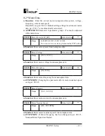
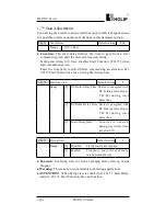
C02.10     Brake Function   


             Default setting 

0


Range 

[0]  Off                 No brake function.


[1]  Resistor Brake   Resistor brake is active.


[2]  AC Brake          AC brake is active.

C02.04     DC Brake Cut In Speed  

          Default setting     0.0HZ


Range 

[0.0 - 400.0 Hz]

● 

Function: 

Set DC-brake cut-in speed to activate DC braking current, 

set in par. C02.01, when ramping down.

  When set to 0 the function is off.

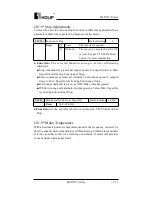
C02.1* Brake Energy Function

Use the parameters in this group for selecting dynamic braking 

parameters.

● 

Function:


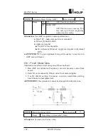
■  Resistor Brake:

  The resistor brake limits voltage in the intermediate circuit when 

the motor acts as generator. Without brake resistor, the frequency 

converter eventually trips.

  The resistor brake consumes surplus energy resulting from motor 

braking. A frequency converter with brake stops a motor faster 

than without a brake, which is used in many applications. Requires 

connection of external brake resistor. An alternative to the resistor 

brake is the AC brake.

■  AC Brake:

  The AC brake consumes surplus energy by creating power loss in 

the motor.

  It is important to keep in mind that an increase in power loss causes 

motor temperature to rise.

● 

ATTENTION!

  Resistor brake is only functional in frequency 

converters with integrated dynamic brake. An external resistor must 

be connected.

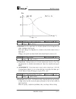
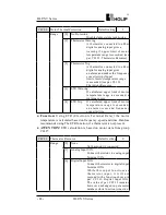
C02.11     Brake Resistor (ohm)   

          Default setting      *Ω


Range 

[5 - 5000 Ω]

● 

Function:

 Set brake resistor value.

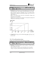
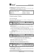
C02.16     AC Brake, Max current  

          Default setting      100%


Range 

 [0 - 400 %]

● Function:

 Enter max. permissible current for AC-braking to avoid 

overheating of motor.

  100% equals motor current set in par. C01.24.

Summary of Contents for HLP-NV Series

Page 1: ......

Page 2: ...HLP NV Series ...

Page 3: ......

Page 4: ...ment 11 3 Installation and Direction 11 V Wiring 12 1 Main Circuit Wiring Schematic Diagram 12 2 Description of Terminal Block 13 3 Basic Connection Diagram 15 4 Switches 15 5 Precautions on Wiring 16 VI Instruction of the LCP Digital Operator 19 1 Description of the LCP Digital Operator 19 2 Programming with LCP 19 VII Parameter Overview 25 VIII Parameter Descriptions 37 IX Maintenance Fault Info...

Page 5: ...ices 96 Appendix 1 Mounting Dimensions of HOLIP NV inverters 96 Appendix 2 Mounting Dimensions of LCP Digital operator 98 Appendix 3 Braking Resistor Disposition 98 Appendix 4 Simple Example of Appliaction 99 Appendix 5 User s feedback 106 ...

Page 6: ...o make sure the safe use of the inverter In case of any doubt please contact our local agent for consultation Our professional persons are willing and ready to serve you The manual is subject to change without notice Danger indicates wrong use may kill or injure people Caution indicates wrong use may damage the inverter or mechanical system Danger Be sure to turn off the input power supply before ...

Page 7: ...Check if each terminal is tightly locked and if there is any foreign article inside the inverter Check if the operator buttons are all right Check if the optional components you ordered are contained Check if there is a certificate of qualification and a warranty card Caution Motor overload protection is included in the default settings Parameter C01 90 Motor thermal protection is set to value ETR...

Page 8: ... Version A 2 Nameplate Description of HLP NV Series Inverter Model HLP NV 0D75 23 A Voltage Rating 21 1 Phase AC 220V 23 3 Phase AC 220V 43 3 Phase AC 380V Inverter Capacity 0 D 75 means 0 75KW Serial No NV means NV series Trade Mark HOLIP ...

Page 9: ...ed to line zero Otherwise it will easily cause the protection or errors of the inverter Caution Do not carry the front cover of the inverter directly when handling It should be handled with the base to prevent the fall off of the front cover and avoid the dropping of the inverter which may possibly cause the injuries to people and the damages to the inverter Mount the inverter on a metal or other ...

Page 10: ... must be installed because of the requirements of process and others it must be ensured that the inverter has no output when the switch acts In addition it is forbidden to install any capacitor for improvement of power factor or any varistor against thunder at the output Otherwise it will cause malfunctions tripping protection and damages of components of the inverter Please remove them as shown i...

Page 11: ...e frequency of 50Hz 2 During the Power up Danger Do not plug the connectors of the inverter during the power up to avoid any surge into the main control board due to plugging which might cause the damage of the inverter Always have the protective cover in place before the power up to avoid electrical shock injury 3 During the Operation Danger Never connect or disconnect the motor set while the inv...

Page 12: ... been disconnected linkage of DC intermediate circuit Be aware that there may be high voltage on the DC link even when the LEDs are turned off Before touching any potentially live parts of the VLT Micro wait at least as follows 200 240 V 0 4 1 5 kW wait at least 4 minutes 380 480 V 0 75 2 2 kW wait at least 4 minutes Shorter time is allowed only if indicated on the nameplate for the specific unit ...

Page 13: ... 240V 50 60Hz 0 75 4 2 0 75 HLPNV01D523A 3 200 240V 50 60Hz 1 5 6 8 1 5 HLPNV02D223A 3 200 240V 50 60Hz 2 2 9 6 2 2 HLPNV03D723A 3 200 240V 50 60Hz 3 7 15 2 3 7 HLPNV0D3743A 3 380 480V 50 60Hz 0 37 1 2 0 37 HLPNV0D7543A 3 380 480V 50 60Hz 0 75 2 2 0 75 HLPNV01D543A 3 380 480V 50 60Hz 1 5 3 7 1 5 HLPNV02D243A 3 380 480V 50 60Hz 2 2 5 3 2 2 HLPNV03D043A 3 380 480V 50 60Hz 3 0 7 2 3 0 HLPNV04D043A 3 ...

Page 14: ...cation Frequency setting Control terminals Programmable digital inputs Number 5 terminal nos RUN F R RST JOG EMS Voltage level 0 24V DC PNP OR NPN Maximum input 28V DC Logic Voltage level PNP 0 5VDC 1 10VDC NPN 0 19VDC 1 14VDC Input resistance 4KΩ Anology inputs Voltage Number 1 terminal nos VIN Voltage level 0 10V DC Maximum input 20V DC Input resistance 10KΩ Current Number 2 terminal nos VIN AIN...

Page 15: ...sink ensures that the frequency converter trips if the temperature reaches 95 C 5 C An overload temperature cannot be reset until the temperature of the heatsink is below 70 C 5 C Guideline these temperatures may vary for different power sizes enclosures etc The frequency converter is protected against short circuits on motor terminals U V W The frequency converter is protected against earth fault...

Page 16: ...e stored for a long time make sure to power it up one time within a year and the power up time should be at least above five hours When powered up the voltage must be increased slowly with a voltage regulator to the rated voltage value 2 Installation Site and Environment The inverter should be installed at the following location Ambient temperature 5 to 40 with good ventilation No water drop and l...

Page 17: ...l it again If the inverter is installed on a loose surface stress may cause damage of parts in the main circuit so as to damage the inverter The inverter should be installed on non combustible materials such as iron plate If several inverters are installed upper and lower together in one cabinet please add heat dissipation plates and leave enough space between the inverters ...

Page 18: ...t interrupter Use one of anti high harmonic Electromagnetic contactor Note Do not use the electromagnetic contactor as the on off button of power supply for the inverter AC reactor It is recommended to install an AC reactor for power factor improvement if the input capacity is more than 1000KVA Inverter Be sure to make correct connections of the main circuit wires and control signal wires of the i...

Page 19: ...r both single three phase single phase connected to L and N U V W Output terminal of the inverter UDC BR Connector for braking resistor optional UDC Connector for DC reactor Ground terminal the third method of grounding for 220V and special grounding for 380 V of Electrical Engineering Regulations Symbol Function Description Default setting setting EV Common Terminal of Digital and Control Signals...

Page 20: ...nals must be connected correctly as the following wiring circuit diagrams The following diagram shows the Default setting standard connection of Model HLP NV Symbol Function Description Default setting setting EMS Multi Digital Input Bit0 AO Multi Analog Output 0 4 20mA 10V Power Supply for Analog Setting 10V VIN Multi Analog input Voltage GND Analog Ground AIN Multi Analog input 0 4 20mA FA FB FC...

Page 21: ...gineering regulations to ensure the safety It is better to use shielded wire or wire and conduit for power cord and ground the shielded layer or two ends of wire conduit Be sure to install a Non Fuse Breaker NFB between the power supply and the input terminals L1 L2 L3 If using ground fault circuit interrupter please choose one corresponding to high frequency Never connect AC power to the output t...

Page 22: ...e current will have unfavorable effect on the inverter and other equipment Model NFB A Input wire mm2 Output wire mm2 Control wire mm2 HLPNV0D1821A 16 2 5 2 5 0 5 HLPNV0D3721A 16 2 5 2 5 0 5 HLPNV0D7521A 16 2 5 2 5 0 5 HLPNV01D521A 16 2 5 2 5 0 5 HLPNV02D221A 32 4 4 0 5 HLPNV0D2523A 16 2 5 2 5 0 5 HLPNV0D3723A 16 2 5 2 5 0 5 HLPNV0D7523A 16 2 5 2 5 0 5 HLPNV01D523A 32 2 5 2 5 0 5 HLPNV02D223A 32 4...

Page 23: ...s The third grounding method Grounding resistance should be 100Ω or lower 380V class The special third grounding method Grounding resistance should be 10Ω or lower Choose grounding wires according to the basic length and size of the technical requirements of the electric equipment Do avoid sharing grounding wire with other large power equipment such as electric welder power machine etc The groundi...

Page 24: ...scription of the LCP Digital Operator LCP with potentiometer LCP without potentiometer 2 Programming with LCP 2 1 LCP introduction 1 5 numeric displays 2 8 LEDs FWD REV Hz A R MIN HAND OFF RESET AUTO 3 7 keys MENU ENTER HAND OFF RESET AUTO 4 1 potentiometer only for type OP VB02 ...

Page 25: ...nu items The top level menu contains two menu items status menu parameter editing menu These two items can be explored by pressing MENU key 2 3 Mode keys and potentiometer Mode Keys are used to send Hand OFF Reset Auto request to the drive It is related to the reference site selection Local or Remote The yellow LEDs indicate the certain active mode ...

Page 26: ... potentiometer will work as the arrow keys i e controlling the local reference from 0 to max reference C03 03 If the LCP does not contain a potentiometer the arrow keys are used to set reference In auto mode the potentiometer will act as an extra analog input to the system It is selected deselected as the other analog inputs see C03 15 to C03 18 C06 81 C06 82 are used to scale the potentiometer in...

Page 27: ...meter editing menu 2 Pressing key to select group No C03 00 3 Pressing ENTER key to edit parameter No then pressing key to select parameter No C03 17 4 Holding down ENTER key to go to the value edting menu then pressing to edit the value of the parameterto 21 then holding down ENTER key to confirm the change till END was displayed ...

Page 28: ...HLP NV Series HLP NV Series 23 2 4 2 Readout and indicator The readout parameters toggled by pressing ENTER key The below table shows the screen of displaying every readout parameter ...

Page 29: ... be lit Alarm description when alarm occurred the LEDs of Hz A and R MIN will flash and the drive will trip A trip can be cancelled by pressing reset or in some cases automatically A locked trip canbe cancelled by cutting off mains and restarting the drive The motor direction is indicated by the leds of FWD and REV ...

Page 30: ...Only 1 C00 42 Auto on Key on LCP 0 Disabled 1 Enabled 1 C00 60 Menu locked 0 Disabled 1 Enabled 0 Load Motor C01 00 Configuration Mode 0 Speed open loop 3 Process 0 C01 01 Motor Control Principle 0 V F 1 VVC 1 C01 03 Torque Characteristics 0 Constant torque 2 Automatic Energy Optim 0 C01 05 Local Mode Configuration 0 Speed Open Loop 2 As config in param C01 00 2 C01 20 Motor Power kW HP 0 09 kW 0 ...

Page 31: ...Speed Load Compensation 0 199 100 C01 61 High Speed Load Compensation 0 199 100 C01 62 Slip Compensation 400 399 100 C01 63 Slip Compensation Time Constant 0 05 5 00 s 0 10s C01 71 Start Delay 0 0 10 0 s 0 0S C01 72 Start Function 0 DC hold delay time 1 DC brake delay time 2 Coast delay time 2 C01 73 Flying Start 0 Disabled 1 Enabled 0 C01 80 Function at Stop 0 Coast 1 DC hold 0 C01 82 Min Speed f...

Page 32: ...t 0 00 100 00 A 0 00A C02 22 Activate Brake Speed Hz 0 0 400 0 Hz 0 0HZ Reference Ramps C03 00 Reference Range 0 Min Max 1 Max Max 0 C03 02 Minimum Reference 4999 000 4999 000 0 000 C03 03 Maximum Reference 4999 000 4999 000 50 000 C03 10 Preset Reference 100 00 100 00 0 00 C03 11 Jog Speed Hz 0 0 400 0 Hz 5 0Hz C03 12 Catch up slow Down Value 0 00 100 00 0 00 C03 14 Preset Relative Reference 100 ...

Page 33: ...Time 0 05 3600 00S 3 00 15 00S C03 52 Ramp 2 Ramp down Time 0 05 3600 00S 3 00 30 00S C03 80 Jog Ramp Time 0 050 3600 000S 3 00 15 00S C03 81 Quick Stop Ramp Time 0 05 3600 00S 3 00 30 00S Limits Warnings C04 10 Motor Speed Direction 0 Clockwise 1 CounterClockWise 2 Both 2 C04 12 Motor Speed Low imit Hz 0 0 400 0Hz 0 0Hz C04 14 Motor Speed High Limit Hz 0 0 400 0Hz 65 0Hz C04 16 Torque Limit Motor...

Page 34: ...ze reference 20 Freeze output 21 Speed up 22 Speed down 23 Setup select bit 0 26 Precise Stop Inverse Only for C05 15 27 Start Precise Stop Only for C05 15 28 Catch up 29 Slow down 32 Pulse Input Only for C05 15 34 Ramp bit 0 60 Counter A up 61 Counter A down 62 Reset counter A 63 Counter B up 64 Counter B down 65 ResetCounterB 8 C05 11 Terminal F R Digital Input 10 C05 12 Terminal RST Digital Inp...

Page 35: ...o thermal warning 24 Ready Voltage ok 25 Reverse 26 Bus ok 28 Brake NoWarn 2 9 B r a k e r e a d y NoFault 30 BrakeFault IGBT 32 Mech brake control 36 Control word bit 11 51 Local ref active 52 Remote ref active 53 No alarm 54 Start cmd active 55 Running reverse 56 Drive in hand mode 57 Drive in auto mode 60 Comparator 0 61 Comparator 1 62 Comparator 2 63 Comparator 3 70 Logic rule 1 71 Logic rule...

Page 36: ...ed 5 Stop and trip 0 C06 10 Terminal VIN Low Voltage 0 00 9 99V 0 07V C06 11 Terminal VIN High Voltage 0 10 10 00V 10 00V C06 12 Terminal VIN Low Current 0 00 19 99mA 0 14 C06 13 Terminal VIN High Current 0 10 20 00mA 20 00 C06 14 Term VIN Low Ref Feedb Value 4999 000 4999 000 0 000 C06 15 Term VIN High Ref Feedb Value 4999 000 4999 000 50 000 C06 16 Terminal VIN Filter Time Constant 0 01 10 00S 0...

Page 37: ...erence 12 Feedback 13 Motor Current 16 Power 20 BusControl 10 C06 92 Terminal AON Digital Output See par C05 40 0 C06 93 Terminal AON Output Min Scale 0 00 200 00 0 00 C06 94 Terminal AON Output Max Scale 0 00 200 00 100 00 Proess PI Contr olers C07 20 Process CL Feedback 1 Resource 0 NoFunction 1 Analog Input VIN 2 Analog Input AIN 8 PulseInput33 11 LocalBusRef 0 C07 30 Process PI Normal Inverse ...

Page 38: ...ntrol Word Timeout Function 0 Off 1 Freeze Output 2 Stop 3 Jogging 4 Max Speed 5 Stop and trip 0 C08 06 Reset Control Word Timeout 0 No Function 1 Do reset 0 C08 30 Protocol 0 FC 2 Modbus 0 C08 31 Address 0 126 1 C08 32 FC Port Baud Rate 0 2400 Baud 1 4800 Baud 2 9600 Baud 3 19200 Baud 4 38400 Baud 2 C08 33 FC Port Parity 0 Even Parity 1 Stop Bit 1 Odd Parity 1 Stop Bit 2 No Parity 1 Stop Bit 3 No...

Page 39: ... Function C14 01 Switching Frequency 0 2 kHz 1 4 kHz 2 8 kHz 4 16 kHz 1 C14 03 Overmodulation 0 Off 1 On 1 C14 12 Fu nction at mains imbalance 0 Trip 1 Warning 2 Disabled 0 C14 20 Reset Mode 0 Manual reset 1 AutoReset 1 2 AutoReset 2 3 AutoReset 3 4 AutoReset 4 5 AutoReset 5 6 AutoReset 6 7 AutoReset 7 8 AutoReset 8 9 AutoReset 9 10 AutoReset 10 11 AutoReset 15 12 AutoReset 20 13 Infinite auto res...

Page 40: ...power section of frequency converter C15 42 Voltage View voltage of frequency converter C15 43 Software Version View power section of frequency converter C15 46 Frequency Converter Order No View ordering number for re ordering C15 48 LCP Id No View LCP ID number C15 51 Frequency Converter Serial No View frequency converter serial number Data Readouts C16 00 Control Word 0 65535 0 C16 01 Reference ...

Page 41: ... Pulse Reference 200 0 200 0 0 0 C16 52 Feedback Unit 4999 000 4999 000 0 000 C16 60 Digital Input RUN F R RST EMS 0 1111 0 C16 61 Digital Input JOG 0 1 0 C16 62 A nalog Input VI N volt 0 00 10 00V 0 00 C16 63 A nalog Input VI N current 0 00 20 00mA 0 00 C16 64 Analog Input AIN 0 00 20 00mA 0 00 C16 65 Analog Output AON mA 0 00 20 00mA 0 00 C16 68 Pulse Input 20 5000Hz 20Hz C16 71 Relay Output bin...

Page 42: ... Set up1 and Set up 2 Furthermore a fixed set of Default setting settings can be copied into one or more set ups Some of the advantages of having more than one set up in the frequency converter are Run motor in one set up Active Set up while updating parameters in another set up Edit Set up C00 04 Oper State at Power up Hand Default setting 1 Range 0 Resume Frequency converter starts in same Hand ...

Page 43: ...nge 0 00 9999 00 The value will be shown at 0Hz Function Scale a readout parameter which can be read in par C16 09 C00 32 Custom Readout Max Scale Default setting 100 Range 0 00 9999 00 The value will be shown at the frequency programmed in par C04 14 Function Scale a readout parameter which can be read in par C16 09 C00 4 LCP Keypad The frequency converter can operate in the following three modes...

Page 44: ...ed Hand on key is functional C00 41 Off Reset Key on LCP Default setting 1 Range 0 Disable Off Reset Off reset key has no function 1 Enable Off Reset Stop signal and reset of any faults 2 Enable Reset Only Reset only Stop Off function is disabled C00 42 Auto on Key on LCP Default setting 1 Range 0 Disabled Auto on key has no function 1 Enabled Auto on key is functional Parameter group 1 Load Motor...

Page 45: ...s C01 05 Local Mode Configuration Default setting 2 Range 0 Speed Open Loop 2 As configuration in par C01 00 Function This parameter is only relevant when parameter C01 00 Configuration Mode is set to Process Closed Loop 3 The parameter is used for determining the reference or setpoint handling when changing from Auto Mode to Hand Mode on the LCP 0 In Hand Mode the drive always runs in Open Loop c...

Page 46: ...Function Enter motor power from nameplate data C01 22 Motor Voltage Default setting Range 50 0 999 0 V Function Enter motor voltage from nameplate data C01 23 Motor Frequency Default setting 50 Range 20 400 Hz Function Enter motor frequency from nameplate data ATTENTION Changing this parameter affects motor nominal speed set in par C01 25 C01 24 Motor Current Default setting Range 0 01 26 00 A Fun...

Page 47: ...e Apply start signal on Terminal RUN ATTENTION To gain optimum tuning of frequency converter run AMT on a cold motor C01 3 Adv Motor Data Adjust advanced motor data using one of these methods 1 Run AMT on cold motor Frequency converter measures value from motor 2 Enter X1 value manually Obtain value from motor supplier 3 Use X1 default setting Frequency converter establishes setting based on motor...

Page 48: ...unction This parameter enables different thermal load on motor when running at low speed C01 52 Min Speed Norm Magnet Hz Default setting 0 0HZ Range 0 0 10 0 Hz Function Use this parameter along with par C01 50 Motor Magnetizing at Zero Speed Set frequency required for normal magnetizing current If frequency is set lower than motor slip frequency par C01 50 Motor Magnetizing at Zero Speed is inact...

Page 49: ...on 6 definable voltages and frequencies see below figure Simplify V F characteristics by merging 2 or more points voltages and frequencies respectively are set equal ATTENTION For par C01 56 the following applies 0 1 2 3 4 5 C01 6 Load Dependent setting Parameters for adjusting the load dependent motor settings C01 60 Low Speed Load Compensation Default setting 100 Range 0 199 Function Use this pa...

Page 50: ... 399 Function Compensation for load dependent motor slip Slip compensation is calculated automatically based on rated motor speed nM N ATTENTION This function is only active when par C01 00 Configuration Mode is set to Speed Open Loop 0 and when par C01 01 Motor Control Principle is set to VVC 1 C01 63 Slip Compensation Time Constant Default setting 0 10 s Range 0 05 5 00 s Function 0 10 s 0 05 5 ...

Page 51: ...tive during Start delay time C01 72 Start Function Default setting 2 Range 0 DC Hold Delay Time Motor is energized with DC holding current par C02 00 during start delay time 1 DC Brake Delay Time Motor is energized with DC braking current par C02 01 during start delay time 2 Coast Delay Time I nve r t e r i s c o a s t e d during start delay time inverter off C01 73 Flying Start Default setting 0 ...

Page 52: ...or Activating Functions at Stop Start command is removed standby and output speed is ramped down to Min Speed for Activating Functions at Stop DC brake command is given and DC brake time has passed While running and calculated output speed is below Min Speed for Activating Functions at Stop C01 82 Min Speed for Funct at Stop Hz Default setting 0 0HZ Range 0 0 20 0 Hz Function Set the speed at whic...

Page 53: ... either digital or analog input gives a warning if upper limit of motor temperature range is exceeded see par C01 93 Thermistor Resource 2 Thermistor Trip A thermistor connected to either digital or analog input gives an alarm and makes the frequency converter trip if upper limit of motor temperature range is exceeded see par C01 93 Thermistor Resource 3 ETR Warning If calculated upper limit of mo...

Page 54: ... at Stop Enter a value for holding current as a percentage of the rated motor current set in par C01 24 Motor Current 100 DC holding current corresponds to IM N ATTENTION Avoid 100 current too long as it may overheat the motor C02 01 DC Brake Current Default setting 50 Range 0 100 Function Set DC current needed to brake rotating motor Activate DC brake in one of the four following ways DC brake co...

Page 55: ...esistor brake consumes surplus energy resulting from motor braking A frequency converter with brake stops a motor faster than without a brake which is used in many applications Requires connection of external brake resistor An alternative to the resistor brake is the AC brake AC Brake The AC brake consumes surplus energy by creating power loss in the motor It is important to keep in mind that an i...

Page 56: ...releases the brake when activated The brake activates if frequency converter trips or a coast command is given Furthermore it activates when motor speed is ramped down below the speed set in par C02 22 Active Brake Speed C02 20 Release Brake Current Default setting 0 00A Range 0 00 100 A Function Select motor current at which mechanical brake releases Warning If start delay time has passed and mot...

Page 57: ... range of reference and feedback signals Values can be both positive and negative unless par C01 00 Configuration Mode is set to Process Closed Loop 3 In that case only positive values are allowed C03 02 Minimum Reference Default setting 0 000 Range 4999 000 4999 000 Function Enter value for minimum reference The sum of all internal and external referneces are clamped limited to the minimum refere...

Page 58: ...mum Reference However there are exceptions if par C03 00 is set to Min Max 0 Example 1 Par C03 02 is set to 20 and par C03 03 is set to 50 In this case 0 0 and 100 50 Example 2 Par C03 02 is set to 70 and par C03 03 is set to 50 In this case 0 0 and 100 70 C03 11 Jog Speed Hz Default setting 5 0HZ Range 0 0 400 0 Hz Select speed to function as jog speed Function Jog speed is a fixed output speed a...

Page 59: ...ation below is multiplied with actual reference labelled X in illustation This product is added to actual reference X X Y 100 C03 15 Reference Resource 1 Default setting 1 Range 0 No Function No reference signal is defined 1 Analog Input VIN Use signals from analog Input VIN as reference see par C06 1 2 Analog Input AIN Use signals from analog Input AIN as reference see par C06 2 8 Pulse input Use...

Page 60: ... Potentiometer U s e s i g n a l s f r o m L C P potentiometer as reference Function See Par C03 15 for description C03 17 Reference Resource 3 Default setting 11 Range 0 No Function No reference signal is defined 1 Analog Input VIN Use signals from analog Input VIN as reference 2 Analog Input AIN Use signals from analog Input AIN as reference 11 Local Bus Ref Use signals from local bus as referen...

Page 61: ...ng reference source 21 LCP Potentiometer Select LCP potentiometer as relative scaling reference source Function Select the source for a variable value to be added to the fixed value defined in par C03 14 Preset Relative Reference 3 4 Ramp 1 A linear ramp is characterized by ramping up at a constant speed until the desired motor speed has been reached Some overshoot may be experienced when reaching...

Page 62: ... over voltage limit C03 40 Ramp 1 Type Default setting 0 Range 0 Linear Constant acceleration deceleration 2 S ramp Smooth jerk compensated acceleration deceleration Function Enter ramp up time from 0 Hz to rated motor speed nM N set in par C01 25 Choose a ramp up time ensuring that output current does not exceed current limit set in par C04 18 during ramping only for NV4 NV5 C03 41 Ramp 1 Ramp up...

Page 63: ... 05 3600 s Function Enter ramp down time from rated motor speed nM N in par C01 25 to 0 Hz Choose a ramp down time that does not cause over voltage in inverter due to regenerative operation of motor Furthermore generated current must not exceed current limit set in par C04 18 only for NV4 NV5 C03 52 Ramp 2 Ramp down Time Default setting 3 00 30 00S Range 0 05 3600 s C03 8 Other Ramps This section ...

Page 64: ...tor Speed High Limit par C04 14 Function A linear ramp applicable when Q stop is activated See par C05 1 selection 4 only for NV4 NV5 C03 81 Quick Stop Ramp Time Default setting 3 00 30 00S Range 0 05 3600 s Parameter group 4 Motor Limits Parameter group for configuring limits and warning C04 1 Motor Limits Use these parameters for defining the speed torque and current working range for the motor ...

Page 65: ...t to default when changing settings in par C01 00 to C01 25 Load Motor C04 17 Torque Limit Generator Mode Default setting 100 Range 0 400 C04 5 Adjustable Warnings Parameter group containing adjustable warning limits for current speed reference and feedback Warnings are shown in display programmed output or serial bus Function Use this parameter to set a lower limit for the current range If curren...

Page 66: ... Make sure to enter the opposite limit of that in par C04 61 Speed Bypass From Hz C04 63 Bypass Speed To Hz Default setting 0 0Hz Range 0 0 400 0 Hz Parameter group 5 Digital In Out The following describes all digital input command functions and signals C05 1 Digital Inputs Parameters for configuring the functions for the input terminals The digital inputs are used for selecting various functions ...

Page 67: ...p inverted input NC The frequency converter resets and leaves the motor in free mode 4 Quick stop inverse Inverted input NC Generates a stop in accordance with the quick stop ramp time set in par C03 81 When motor stops shaft is in free mode 5 DC brake inv Inverted input for DC braking NC Stops motor by energizing it with DC current for a certain time period see par C02 01 Function is only active ...

Page 68: ...ef bit 0 16 see par C03 10 18 Preset ref bit 2 Same as preset ref bit 0 16 19 Freeze reference Freeze actual reference The frozen reference is now the point of enable condition for Speed up and Speed down to be used If Speed up down is used speed change always follows ramp 2 par C03 51 and C03 52 in the range par C03 02 Minimum Reference par C03 03 Maximum Reference 20 Freeze output Freeze the act...

Page 69: ...e function is available for Terminal EMS only 27 Start precise stop As 26 but including Start 28 Catch up Select Catch up Slow down to increase or reduce the resulting reference value by the percentage set in par C03 12 29 Slow down Same as Catch up 28 32 Pulse input only Terminal EMS Select Pulse input when using a pulse sequence as either reference or feedback Scaling is done in par group C05 5 ...

Page 70: ...e present 8 Run on ref No Warning Motor runs at reference speed 9 Alarm An alarm activates output 10 Alarm on Warning An alarm or warning activates output 12 Out of Current Range Motor current is outside range set in parameters C04 50 and C04 51 13 Below Current low Motor current is lower than set in par C04 50 14 Above Current high Motor current is higher than set in par C04 51 21 Thermal Warning...

Page 71: ... control of external mechanical brake see parameter group C02 2 36 Control Word Bit 11 Bit 11 in control word controls relay 51 Local Ref Active 52 Remote Ref Active 53 No Alarm 54 Start Cmd Active 55 Running Reverse 5 5 Pulse Input Set par C05 15 to choice 32 pulse input Now Terminal EMS handles a pulse input in the range from Low frequency par C05 55 to High frequency par C05 56 Scale frequency ...

Page 72: ...up 6 Analog In Out Parameter group for configuring analog inputs and outputs C06 0 Analog I O Mode Parameter group for setting up the analog I O configuration Function The Live Zero function is used for monitoring the signal on an analog input If the signal disappears a Live Zero warning is reported Set delay time before Live Zero Timeout Function is applied par C06 01 If the signal reappears duri...

Page 73: ... 41 4 Max Speed Frequency converter ramps to Motor Speed High Limit see par C04 14 5 Stop and Trip Frequency converter ramps down to 0 Hz and then trips Remove live zero condition and activate reset before restarting the frequency converter Function Function is activated if input signal is below 50 of value set in parameters C06 10 C06 12 or C06 22 C06 1 Analog Input 1 Parameters for configuring s...

Page 74: ...te the Live Zero Timeout function in par C06 01 C06 12 Terminal VIN Low Current Default setting 0 14 Range 0 00 19 99 mA Enter low current value Function This reference signal should correspond to the maximum reference value set in par C06 15 C06 13 Terminal VIN High Current Default setting 20 00 Range 0 10 20 00 mA Enter high current value Function The scaling value corresponding to the low volta...

Page 75: ...This reference signal should correspond to minimum reference value set in par C03 02 Warining The value must be set to min 2 mA in order to activate the Live Zero Timeout function in par C06 01 C06 22 Terminal AIN Low Current Default setting 0 14 Range 0 00 19 99 mA Enter low current value Function This reference signal should correspond to the high current value set in par C06 25 C06 23 Terminal ...

Page 76: ...reference value The reference value corresponding to potentiometer turned fully counterclockwise 0 degrees C06 81 LCP potm Low Ref Feedb Value Default setting 0 000 Range 4999 000 4999 000 Function The scaling value corresponding to the maximum reference feedback value set in par C03 03 Enter high reference value The reference value corresponding to potentiometer turned fully clockwise 200 degrees...

Page 77: ...lues up to 100 can never be higher than corresponding setting in par C06 52 C06 93 Terminal AON Output Min Scale Default setting 0 00 Range 0 00 200 00 Function Scale maximum output of selected analog signal at Terminal AON Set value to maximum value of current signal output Scale output to give a current lower than 20 mA at full scale or 20 mA at an output below 100 of maximum signal value If 20 ...

Page 78: ...a speed increase Feedback less than setpoint result in a speed reduction C07 20 Process CL Feedback 1 Resource Default setting 0 Range 0 No Function 1 Analog Input VIN 2 Analog Input AIN 8 Pulse Input 33 11 Local Bus Ref Parameter group 7 Controllers Parameters group for configuring application controls C07 2 Process Ctrl Feedb Select feedback sources and handling for Process PI Control Function S...

Page 79: ... integrator provides an increasing gain at a constant error between the set point and the feedback signal The integral time is the time needed by the integrator to reach the same gain as the proportional gain C07 34 Process PI Integral Time Default setting 9999 00s Range 0 01 9999 00 s Function The FF factor sends a part of the reference signal around the PI controller which then only affects part...

Page 80: ...cation 8 0 General Settings Use this parameter group for configuring the general settings for communication Function The setting in this parameter overrules settings in par C08 50 to C08 56 C08 02 Control Word Source Default setting 1 Range 0 None Function is inactive 1 FC RS485 Monitoring control word source is done via serial communication port RS485 Function Enter time to pass before control wo...

Page 81: ...rder to restart either via LCP or digital input Function Select the action to be taken in case of a timeout C08 06 Reset Control Word Timeout Default setting 0 Range 0 No Function Control word timeout is not reset 1 Do Reset Control word timeout is reset and parameter goes into No Function state Function Resetting the control word timeout will remove any timeout function 8 3 FC Port Settings Param...

Page 82: ...Port Parity Default setting 0 Range 0 Even Parity 1 stopbit 1 Odd parity 2 No Parity 1 stopbit Select this for Modbus RTU 3 No Parity 2 stopbit Function This parameter only affects Modbus as FC bus always has even parity Function Specify minimum delay time between receiving a request and transmitting a response C08 35 Minimum Response Delay Default setting 0 010s Range 0 001 0 500 s Function Speci...

Page 83: ... via digital input and or bus C08 51 Quick Stop Select Default setting 3 Range 0 Digital Input Activation via a digital input 1 Bus Activation via serial communication port 2 LogicAnd Activation via serial communication port and a digital input 3 LogicOr Activation via serial communication port or a digital input Function Select control of quick stop function via digital input and or bus C08 52 DC...

Page 84: ...Activation via a digital input 1 Bus Activation via serial communication port 2 LogicAnd Activation via serial communication port and a digital input 3 LogicOr Activation via serial communication port or a digital input Function Select control of reversing function via digital input and or bus C08 55 Set up Select Default setting 3 Range 0 Digital Input Activation via a digital input 1 Bus Activat...

Page 85: ...s feedback 1 Default setting 0 Range 0 0x8000 0x7FFF Parameter group 14 Special Functions Parameter group for configuring special frequency converter functions 14 0 Inverter Switching Parameters for configuring the inverter switching C14 01 Switching Frequency Default setting 1 Range 0 2 KHZ 1 4KHZ 2 8KHZ 4 16KHZ Function Select the switching frequency in order to minimize e g acoustic noise and p...

Page 86: ...15 Performs fifteen automatic resets after tripping 12 AutoReset 20 Performs twenty automatic resets after tripping 13 Infinite auto reset Performs an infinite number of automatic resets after tripping Function This feature allows more accurate speed control near and over nominal speed 50 60 Hz Another advantage with overmodulation is the ability of staying at a constant speed even though mains is...

Page 87: ...nverter runs normal operation 2 Initialization Resets all parameters to default settings except for C15 03 C15 04 and C15 05 Frequency converter resets during next power up Par 14 22 also reverts to default setting Normal Operation 0 Function Use this parameter for specifying normal operation or to initialize all parameters except par C15 03 C15 04 and C15 05 C14 26 Action At Inverter Fault Defaul...

Page 88: ...nction View power consumption in kWh as a mean value over one hour Reset counter in par C15 06 Reset kWh Counter C15 01 Running Hours Default setting 0 Range 0 2147483647 Function View power consumption in kWh as a mean value over one hour Reset counter in par C15 06 Reset kWh Counter C15 02 kWh Counter Default setting 0 Range 0 65535 Function View number of times frequency converter has been powe...

Page 89: ... reset 1 Reset Counter Counter is reset Function This parameter cannot be selected via serial port RS 485 15 3 Fault Log This parameter group contains a fault log showing reasons for the ten latest trips Function View error code and look it up in VLT Micro Design Guide C15 30 Fault Log Error Code Default setting 0 Range 0 255 C15 4 Drive Identification Parameters containing read only information a...

Page 90: ... control alarm warning and status words 16 0 General Status Parameters for reading the general status e g the calculated reference the active control word status Function View latest valid control word sent to frequency converter via serial communication port C16 00 Control Word Default setting 0 Range 0 65535 Function View total remote reference Total reference is sum of pulse analog preset LCP p...

Page 91: ...Default setting 0 00 Range 0 00 9999 00 Function View output power in kW C16 10 Power kW Default setting 0kw Range 0 99 kW Function View output power inHp C16 11 Power hp Default setting 0 H p Range 0 99 Hp Function View motor phase voltage C16 12 Motor Voltage Default setting 0 0 Range 0 0 999 9 V Function View output frequency in Hz C16 13 Frequency Default setting 0 0HZ Range 0 0 400 0 Hz Funct...

Page 92: ...verter current 150 C16 37 Inv Max Current Default setting 0 00A Range 0 1 10000 00 A C16 5 Ref Feedb Parameters for reporting the reference and feedback input Function View sum of all external references in percent C16 50 External Reference Default setting 0 0 Range 200 0 200 0 Function View actual pulse input converted to a reference in percent C16 51 Pulse Reference Default setting 0 0 Range 200...

Page 93: ...nput current on analog input terminal C16 63 Analog Input VIN current Default setting 0 00 Range 0 00 20 00 mA Function View actual value at Input AIN either as reference or protection value C16 64 Analog Input AIN Default setting 0 00 Range 0 00 20 00 mA Function View output current on analog Output AO C16 65 Analog Output AON mA Default setting 0 00 Range 0 00 20 00 mA Function View input freque...

Page 94: ...FC Port C16 86 FC Port REF 1 Default setting 0 Range 200 200 16 9 Diagnosis Read Out Parameters displaying alarm warning and extended status words Function View alarm word sent via serial communication port in hex code C16 90 Alarm Word Default setting 0 Range 0 0xFFFFFFFF Function View warning word sent via serial communication port in hex code C16 92 Warning Word Default setting 0 Range 0 0xFFFF...

Page 95: ...ll result in the short circuit of circuit board Keep the inverter clean free from dust oil mist and moisture after the installation 2 Periodical Inspection and Maintenance items Check whether the power supply voltage conforms to the rated voltage of the inverter Pay special attention to that whether there is any damage on the power supply wires and the motor Check whether the wiring terminals and ...

Page 96: ...se contact holip 2 Motor cannot rotate Make sure no warning or alarm occured If any warning or alarm occurred please refer to corresponding troubleshooting section If no warning or alarm occurred please refer to item 5 Please make sure if input voltage is correct and refer to item 4 if it is correct 3 Braking function cannot take effect Please refer to braking function section 4 No fault message o...

Page 97: ...or too high voltage imbalance Check supply voltage DC over voltage Intermediate circuit voltage exceeds limit DC under voltage Intermediate circuit voltage drops below voltage warning low limit Inverter overloaded More than 100 overload for too long Motor ETR over temperature Motor is too hot due to more than 100 overload for too long Torque limit Torque exceeds value set in either par C4 16 or C4...

Page 98: ...harge from output phases to ground Short Circuit Short circuit in motor or on motor terminals Control word timeout No communication to frequency converter Brake resistor short circuited Brake transistor is short circuited thus brake function is disconnected Brake chopper short circuited Brake transistor is short circuited thus brake function is disconnected ...

Page 99: ...r temp Heat sink cut out temperature has been reached Motor phase U missing Motor phase U is missing Check the phase Motor phase V missing Motor phase V is missing Check the phase Motor phase W missing Motor phaseW is missing Check the phase Internal fault Contact local HOLIP supplier 24 V supply low External 24 V DC back up power supply may be overloaded ...

Page 100: ... AMT low Inom Motor current is too low Check settings Motor thermistor over temperature Thermistor or thermistor connection is disconneted Mechanical Brake Low Actual motor current has not exceeded release brake current within start delay time window Drive Initialised to Default Value All parameter settings are initialized to default settings Note A Alarm E Warning ...

Page 101: ...ppearance and Installation Dimensions HLPNV0D1821A HLPNV0D3721A HLPNV0D7521A HLPNV01D521A HLPNV02D221A HLPNV0D2523A HLPNV0D3723A HLPNV0D7523A HLPNV01D523A HLPNV02D223A HLPNV03D723A HLPNV0D3743A HLPNV0D7543A HLPNV01D543A HLPNV02D243A HLPNV03D043A HLPNV04D043A HLPNV05D543A HLPNV07D543A HLPNV001143A HLPNV001543A HLPNV18D543A HLPNV002243A ...

Page 102: ...A HLPNV0D7543A NV2 HLPNV01D521A 61 75 178 186 170 Φ4 5 Φ4 5 HLPNV01D523A HLPNV01D543A HLPNV02D243A NV3 HLPNV02D221A 76 90 230 239 196 Φ4 5 Φ4 5 HLPNV02D223A HLPNV03D043A HLPNV03D723A HLPNV04D043A HLPNV05D543A HLPNV07D543A NV4 HLPNV001143A 97 125 273 292 243 Φ7 Φ7 HLPNV001543A NV5 HLPNV18D543A 137 165 316 335 252 Φ7 Φ7 HLPNV002243A Note Type NV2 NV3 NV4 NV5 are embededed with brake unit but NV1 wit...

Page 103: ...KW Braking resistor Specification Braking torque 40 ED Suitable Motor KW KW Ω 1 5 0 8 65 1 6 1 5 2 2 1 50 1 6 2 2 3 7 3 25 1 6 3 7 200 240V Model KW Braking resistor Specification Braking torque 40 ED Suitable Motor KW KW Ω 1 5 0 8 310 1 6 1 5 2 2 1 35 210 1 6 2 2 3 0 2 150 1 6 3 0 4 0 2 4 110 1 6 4 0 5 5 3 80 1 6 5 5 7 5 4 5 65 1 6 7 5 11 5 40 1 6 11 15 9 3 30 1 6 15 18 5 12 7 25 1 6 18 5 22 13 2...

Page 104: ...e extern terminals to control the drive 1 Press AUTO key Digital control and communication control are active only in Auto mode 2 Connect RUN with EV to operate the drive terminal RUN was set to RUN function 3 Analogue input VI AI or the pot On LCP can be used to set reference 4 AMT sequence Automatic motor tuning 1 Stop the drive and make sure motor is at standstill 2 Enter motor nameplate data t...

Page 105: ...terminals of RST JOG EMS to select preset reference C05 10 8 Start C05 12 16 Preset Ref Bit0 C05 13 17 Preset Ref Bit1 C05 15 18 Preset Ref Bit2 C03 02 0 Min reference C03 03 50 Max reference C03 10 0 xx Spped 1 C03 10 1 xx Spped 2 C03 10 2 xx Spped 3 C03 10 3 xx Spped 4 C03 10 4 xx Spped 5 C03 10 5 xx Spped 6 C03 10 6 xx Spped 7 C03 10 7 xx Spped 8 Press Auto key to active Auto mode ...

Page 106: ...fines the setpoint of PI control feedback C07 20 defines the feedback signal of PI control Example Use preset reference C03 10 0 as setpoint Use 4 20mA Analogue input as feedback Parameters setting C03 02 0 C03 03 50 C03 10 0 50 C03 15 C03 16 C03 17 C03 14 C03 18 0 C06 12 4mA C06 13 20mA C06 14 0 C06 15 50 C06 19 1 C07 20 1 VI C07 30 0 C07 31 0 C07 32 0 C07 33 1 00 C07 34 10 00s C07 38 0 C07 39 50...

Page 107: ... 5000 Terminal EMS high frequency C05 57 0 Terminal EMS low value C05 58 50 Terminal EMS high value C16 68 can be Viewew input frequency on EMS Press Auto to active Auto mode Connect RUN with EV to operate the drive C03 11 10 00Hz Jog frequency C03 15 1 C03 16 0 C03 17 0 C03 41 0 5S C03 42 0 5S C03 80 0 5 C04 10 2 C05 10 8 C05 11 11 C05 13 14 C06 10 0V C06 11 10V C06 14 0Hz C06 15 50Hz ...

Page 108: ...5 Main Reactance C01 60 Low Speed Load Compensation C01 61 High Speed Load Compensation C01 62 Slip Compensation C01 63 Slip Compensation Use AMT to optimize motor performance in VVC principle 11 How to display motor speed Example Motor 1440 min 50HZ C00 31 0 C00 32 1440 C04 14 50HZ The custom readout will be the motor speed 12 Use LCP Pot to realize running forward reverse LCP OP VB02 Example Tur...

Page 109: ... MAX 14 2 Stop with the reference of 0HZ Send STX LGE ADR CTW REF CS 02 06 01 043C 0000 3D Hex the frequency converter Return STX LGE ADR STW REF CS 02 06 01 0203 0000 04 Hex 14 3 Read parameter C03 41 Send STX LGE ADR DATA DATA CTW REF CS 02 0E 01 1115 0000 0000 0000 0000 0000 49 Hex the frequency converter Return STX LGE ADR DATA DATA STW REF CS 02 0E 01 2155 0000 0000 012C 0203 0000 55 Hex 14 4...

Page 110: ...01 03 02 000A 3843 12 7 Write single coils Control Word Write the value of parameter to RAM and EEPROM TX 01 05 0040 FF00 8DEE RX 01 05 0040 FF00 8DEE 12 8 Write single register Write parameter Single Word Write C05 11 Address 511 10 1 5109 13F5H TX 01 06 13F5 000B DCBB RX 01 06 13F5 000B DCBB 12 9 Write mutiple coils Write control word and reference frequency Start with the reference of 50HZ TX 0...

Page 111: ... HP C01 22 Motor Voltage C01 23 Motor Frequency 50 C01 24 Motor Current C01 25 Motor Nominal Speed C01 29 Automatic Motor Tuning AMT 0 C01 30 Stator Resistance Rs C01 33 Stator Leakage Reactance X1 C01 35 Main Reactance X2 C01 50 Motor Magnetisation at 0 Speed 100 C01 52 Min Speed Norm Magnet Hz 0 0H z C01 55 V F Characteristic V 0V C01 56 V F Characteristic F 0H z C01 60 Low Speed Load Compensati...

Page 112: ... 14 Preset Relative Reference 0 00 C03 15 Reference Resource 1 1 C03 16 Reference Resource 2 2 C03 17 Reference Resource 3 11 C03 18 Relative Scaling Ref Resource 0 C03 40 Ramp 1 Type 0 C03 41 Ramp 1 Ramp up Time 3 00 15 00S C03 42 Ramp 1 Ramp Down Time 3 00 30 00S C03 50 Ramp 2 Type 0 C03 51 Ramp 2 Ramp up Time 3 00 15 00S C03 52 Ramp 2 Ramp down Time 3 00 30 00S C03 80 Jog Ramp Time 3 00 15 00S ...

Page 113: ...ut Time 10S C06 01 Live Zero TimeoutFunction 0 C06 10 Terminal VIN Low Voltage 0 07V C06 11 Terminal VIN High Voltage 10 00V C06 12 Terminal VIN Low Current 0 14 C06 13 Terminal VIN High Current 20 00 C06 14 Term VIN Low Ref Feedb Value 0 000 C06 15 Term VIN High Ref Feedb Value 50 000 C06 16 Ter m i nal V I N Filter Ti me Constant 0 01 C06 19 Terminal VIN mode 0 C06 22 Terminal AIN Low Current 0 ...

Page 114: ...ol Site 0 C08 02 Control Word Source 1 C08 03 Control Word Timeout Time 1 0S C08 04 Control Word Timeout Function 0 C08 06 Reset Control Word Timeout 0 C08 30 Protocol 0 C08 31 Address 1 C08 32 FC Port Baud Rate 2 C08 33 FC Port Parity 0 C08 35 Minimum Response Delay 0 010S C08 36 Max Response Delay 5 000S C08 50 Coasting Select 3 C08 51 Quick Stop Select 3 C08 52 DC Brake Select 3 C08 53 Start Se...

Page 115: ...Frequency Converter Order No C15 48 LCP Id No C15 51 Frequency Converter Serial No Data Readouts C16 00 Control Word 0 C16 01 Reference Unit 0 000 C16 02 Reference 0 0 C16 03 Status Word 0 C16 05 Main Actual Value 0 00 C16 09 Custom Readout 0 00 C16 10 Power kW 0KW C16 11 Power hp 0HP C16 12 Motor Voltage 0 0 C16 13 Frequency 0 0Hz C16 14 Motor Current 0 00A C16 15 Frequency 0 00 C16 18 Motor Ther...

Page 116: ... C16 61 Digital Input JOG 0 C16 62 Analog Input VIN volt 0 00 C16 63 Analog Input VIN current 0 00 C16 64 Analog Input AIN 0 00 C16 65 Analog Output AO mA 0 00 C16 68 Pulse Input 20Hz C16 71 Relay Output bin 0 C16 72 Counter A 0 C16 73 Counter B 0 C16 86 FC Port REF 1 0 C16 90 Alarm Word 0 C16 92 Warning Word 0 C16 94 Ext Status Word 0 ...

Reviews: