422
13.1.2
Block Diagram
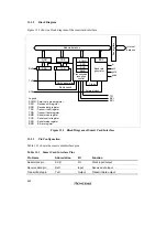
Figure 13.1 shows a block diagram of the smart card interface.
Bus interface
TDR
RSR
RDR
Module data bus
TSR
SCMR
SSR
SCR
Transmission/
reception
control
BRR
Baud rate
generator
Internal
data bus
RxD
TxD
SCK
Parity generation
Parity check
Clock
External clock
φ
φ
/4
φ
/16
φ
/64
TXI
RXI
ERI
SMR
Legend
SCMR : Smart card mode register
RSR
: Receive shift register
RDR
: Receive data register
TSR
: Transmit shift register
TDR
: Transmit data register
SMR
: Serial mode register
SCR
: Serial control register
SSR
: Serial status register
BRR
: Bit rate register
Figure 13.1 Block Diagram of Smart Card Interface
13.1.3
Pin Configuration
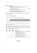
Table 13.1 shows the smart card interface pins.
Table 13.1
Smart Card Interface Pins
Pin Name
Abbreviation
I/O
Function
Serial clock pin
SCK
I/O
Clock input/output
Receive data pin
RxD
Input
Receive data input
Transmit data pin
TxD
Output
Transmit data output
Summary of Contents for H8/3060
Page 10: ......
Page 16: ......
Page 114: ...66 ...
Page 132: ...84 ...
Page 144: ...96 ...
Page 170: ...122 ...
Page 212: ...164 ...
Page 268: ...220 ...
Page 332: ...284 ...
Page 396: ...348 ...
Page 494: ...446 ...
Page 698: ...650 ...
Page 748: ...700 H8 3064F ZTAT B mask version Ports 1 2 5 LED 600 Ω Figure 22 8 Sample LED Circuit ...
Page 777: ...729 H8 3062F ZTAT B mask version Ports 1 2 5 LED 600 Ω Figure 22 14 Sample LED Circuit ...
Page 810: ...762 ...
Page 994: ...946 ...


