xxii
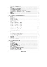
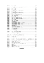
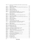
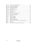
Figure 12.10
Sample Flowchart for Transmitting Multiprocessor Serial Data ....................... 402
Figure 12.11
Example of SCI Transmit Operation (8-Bit Data with Multiprocessor Bit and
One Stop Bit)...................................................................................................... 403
Figure 12.12
Sample Flowchart for Receiving Multiprocessor Serial Data............................ 404
Figure 12.13
Example of SCI Receive Operation (8-Bit Data with Multiprocessor Bit and
One Stop Bit)...................................................................................................... 406
Figure 12.14
Data Format in Synchronous Communication ................................................... 407
Figure 12.15
Sample Flowchart for SCI Initialization ............................................................ 408
Figure 12.16
Sample Flowchart for Serial Transmitting ......................................................... 409
Figure 12.17
Example of SCI Transmit Operation.................................................................. 410
Figure 12.18
Sample Flowchart for Serial Receiving.............................................................. 411
Figure 12.19
Example of SCI Receive Operation ................................................................... 413
Figure 12.20
Sample Flowchart for Simultaneous Serial Transmitting and Receiving .......... 414
Figure 12.21
Receive Data Sampling Timing in Asynchronous Mode ................................... 417
Figure 12.22
Example of Synchronous Transmission ............................................................. 418
Figure 12.23
Operation when Switching from SCK Pin Function to Port Pin Function......... 419
Figure 12.24
Operation when Switching from SCK Pin Function to Port Pin Function
(Example of Preventing Low-Level Output)...................................................... 420
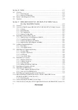
Figure 13.1
Block Diagram of Smart Card Interface ............................................................ 422
Figure 13.2
Smart Card Interface Connection Diagram ........................................................ 430
Figure 13.3
Smart Card Interface Data Format ..................................................................... 431
Figure 13.4
Timing of TEND Flag Setting............................................................................ 437
Figure 13.5
Sample Transmission Processing Flowchart...................................................... 438
Figure 13.6
Relation Between Transmit Operation and Internal Registers ........................... 439
Figure 13.7
Timing of TEND Flag Setting............................................................................ 439
Figure 13.8
Sample Reception Processing Flowchart ........................................................... 440
Figure 13.9
Timing for Fixing Cock Output.......................................................................... 441
Figure 13.10
Procedure for Stopping and Restarting the Clock .............................................. 442
Figure 13.11
Receive Data Sampling Timing in Smart Card Interface Mode ........................ 443
Figure 13.12
Retransmission in SCI Receive Mode................................................................ 445
Figure 13.13
Retransmission in SCI Transmit Mode .............................................................. 445
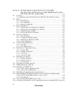
Figure 14.1
A/D Converter Block Diagram .......................................................................... 448
Figure 14.2
A/D Data Register Access Operation (Reading H'AA40).................................. 455
Figure 14.3
Example of A/D Converter Operation (Single Mode, Channel 1 Selected)....... 457
Figure 14.4
Example of A/D Converter Operation (Scan Mode, Channels AN
0
to AN
2
Selected) ............................................................................................................. 459
Figure 14.5
A/D Conversion Timing ..................................................................................... 460
Figure 14.6
External Trigger Input Timing ........................................................................... 461
Figure 14.7
Example of Analog Input Protection Circuit...................................................... 463
Figure 14.8
Analog Input Pin Equivalent Circuit .................................................................. 463
Figure 14.9
A/D Converter Accuracy Definitions (1) ........................................................... 464
Figure 14.10
A/D Converter Accuracy Definitions (2) ........................................................... 465
Figure 14.11
Analog Input Circuit (Example) ......................................................................... 466
Summary of Contents for H8/3060
Page 10: ......
Page 16: ......
Page 114: ...66 ...
Page 132: ...84 ...
Page 144: ...96 ...
Page 170: ...122 ...
Page 212: ...164 ...
Page 268: ...220 ...
Page 332: ...284 ...
Page 396: ...348 ...
Page 494: ...446 ...
Page 698: ...650 ...
Page 748: ...700 H8 3064F ZTAT B mask version Ports 1 2 5 LED 600 Ω Figure 22 8 Sample LED Circuit ...
Page 777: ...729 H8 3062F ZTAT B mask version Ports 1 2 5 LED 600 Ω Figure 22 14 Sample LED Circuit ...
Page 810: ...762 ...
Page 994: ...946 ...

