xxiii
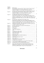
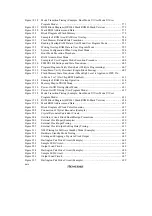
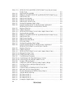
Figure 15.1
D/A Converter Block Diagram .......................................................................... 468
Figure 15.2
Example of D/A Converter Operation................................................................ 473
Figure 16.1
RAM Block Diagram ......................................................................................... 476
Figure 17.1
Block Diagram of Flash Memory....................................................................... 481
Figure 17.2
Example of ROM Area/RAM Area Overlap...................................................... 488
Figure 17.3
Boot Mode.......................................................................................................... 491
Figure 17.4
User Program Mode (Example).......................................................................... 492
Figure 17.5
System Configuration When Using Boot Mode ................................................ 493
Figure 17.6
Boot Mode Execution Procedure........................................................................ 494
Figure 17.7
Measurement of Low Period of Host’s Transmit Data ...................................... 495
Figure 17.8
RAM Areas in Boot Mode ................................................................................. 496
Figure 17.9
User Program Mode Execution Procedure (Example) ....................................... 499
Figure 17.10
FLMCR Bit Settings and State Transitions........................................................ 501
Figure 17.11
Program/Program-Verify Flowchart (32-byte Programming)............................ 503
Figure 17.12
Erase/Erase-Verify Flowchart (Single-Block Erasing) ...................................... 505
Figure 17.13
Flash Memory State Transitions (Modes 5 and 7 (On-Chip ROM Enabled),
High Level Applied to FWE Pin) ....................................................................... 509
Figure 17.14
Example of RAM Overlap Operation ................................................................ 511
Figure 17.15
Memory Map in PROM Mode ........................................................................... 514
Figure 17.16
Power-On/Off Timing (Boot Mode) .................................................................. 517
Figure 17.17
Power-On/Off Timing (User Program Mode).................................................... 518
Figure 17.18
Mode Transition Timing (Example: Boot Mode
→
User Mode
↔
User
Program Mode) .................................................................................................. 519
Figure 17.19
ROM Block Diagram (H8/3062 Mask ROM Version) ...................................... 520
Figure 17.20
Mask ROM Addresses and Data ........................................................................ 521
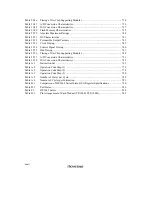
Figure 18.1
Block Diagram of Flash Memory....................................................................... 526
Figure 18.2
Flash Memory Related State Transitions ........................................................... 536
Figure 18.3
Reading Overlap RAM Data in User Mode/User Program Mode ..................... 539
Figure 18.4
Writing Overlap RAM Data in User Program Mode ......................................... 540
Figure 18.5
System Configuration When Using Boot Mode ................................................ 542
Figure 18.6
Boot Mode Execution Procedure........................................................................ 543
Figure 18.7
RAM Areas in Boot Mode ................................................................................. 545
Figure 18.8
Example of User Program Mode Execution Procedure ..................................... 548
Figure 18.9
FLMCR1 Bit Settings and State Transitions...................................................... 550
Figure 18.10
Program/Program-Verify Flowchart (128-Byte Programming) ......................... 555
Figure 18.11
Erase/Erase-Verify Flowchart (Single-Block Erasing) ...................................... 557
Figure 18.12
Flash Memory State Transitions (When High Level is Applied to FWE Pin
in Mode 5 or 7 (On-Chip ROM Enabled)) ......................................................... 561
Figure 18.13
Flowchart of Flash Memory Emulation in RAM ............................................... 562
Figure 18.14
Example of RAM Overlap Operation ................................................................ 563
Figure 18.15
Memory Map in PROM Mode ........................................................................... 565
Figure 18.16
Power-On/Off Timing (Boot Mode) .................................................................. 569
Figure 18.17
Power-On/Off Timing (User Program Mode).................................................... 570
Summary of Contents for H8/3060
Page 10: ......
Page 16: ......
Page 114: ...66 ...
Page 132: ...84 ...
Page 144: ...96 ...
Page 170: ...122 ...
Page 212: ...164 ...
Page 268: ...220 ...
Page 332: ...284 ...
Page 396: ...348 ...
Page 494: ...446 ...
Page 698: ...650 ...
Page 748: ...700 H8 3064F ZTAT B mask version Ports 1 2 5 LED 600 Ω Figure 22 8 Sample LED Circuit ...
Page 777: ...729 H8 3062F ZTAT B mask version Ports 1 2 5 LED 600 Ω Figure 22 14 Sample LED Circuit ...
Page 810: ...762 ...
Page 994: ...946 ...


