352
11.2.2
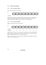
Timer Control/Status Register (TCSR)
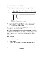
TCSR is an 8-bit readable and writable register. Its functions include selecting the timer mode and
clock source.
Bit
Initial value
Read/Write
7
OVF
0
R/(W)
*
6
WT/IT
0
R/W
5
TME
0
R/W
4
—
1
—
3
—
1
—
0
CKS0
0
R/W
2
CKS2
0
R/W
1
CKS1
0
R/W
Overflow flag
Status flag indicating overflow
Clock select
These bits select the
TCNT clock source
Timer mode select
Selects the mode
Timer enable
Selects whether TCNT runs or halts
Reserved bits
Notes: The method for writing to TCSR is different from that for general registers to prevent
inadvertent overwriting. For details see section 11.2.4, Notes on Register Access.
*
Only 0 can be written, to clear the flag.
Bits 7 to 5 are initialized to 0 by a reset and in standby mode. Bits 2 to 0 are initialized to 0 by a
reset. In software standby mode bits 2 to 0 are not initialized, but retain their previous values.
Bit 7—Overflow Flag (OVF): This status flag indicates that the timer counter has overflowed
from H'FF to H'00.
Bit 7
OVF
Description
0
[Clearing condition]
Cleared by reading OVF when OVF = 1, then writing 0 in OVF
(Initial value)
1
[Setting condition]
Set when TCNT changes from H'FF to H'00
Summary of Contents for H8/3060
Page 10: ......
Page 16: ......
Page 114: ...66 ...
Page 132: ...84 ...
Page 144: ...96 ...
Page 170: ...122 ...
Page 212: ...164 ...
Page 268: ...220 ...
Page 332: ...284 ...
Page 396: ...348 ...
Page 494: ...446 ...
Page 698: ...650 ...
Page 748: ...700 H8 3064F ZTAT B mask version Ports 1 2 5 LED 600 Ω Figure 22 8 Sample LED Circuit ...
Page 777: ...729 H8 3062F ZTAT B mask version Ports 1 2 5 LED 600 Ω Figure 22 14 Sample LED Circuit ...
Page 810: ...762 ...
Page 994: ...946 ...


