532
18.3.3
Erase Block Register 1 (EBR1)
Bit
7
6
5
4
3
2
1
0
EB7
EB6
EB5
EB4
EB3
EB2
EB1
EB0
Initial value
0
0
0
0
0
0
0
0
Read/Write
R/W
R/W
R/W
R/W
R/W
R/W
R/W
R/W
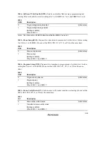
EBR1 is an 8-bit register that specifies the flash memory erase area block by block. EBR1 is
initialized to H'00 by a reset, in hardware standby mode and software standby mode, when a low
level is input to the FWE pin, and when a high level is input to the FWE pin and the SWE bit in
FLMCR1 is not set. When a bit in EBR1 is set to 1, the corresponding block can be erased. Other
blocks are erase-protected. Only one bit can be set in EBR1 and EBR2 together;
do not set two or
more bits at the same time. When the on-chip flash memory is disabled, a read access to this
register will return H'00, and erasing is disabled.
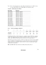
The flash memory block configuration is shown in table 18.5. To erase the entire flash memory,
each block must be erased in turn.
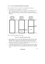
As the H8/3064F-ZTAT B-mask version does not support on-board programming modes in mode
6, EBR1 register bits cannot be set to 1 in this mode.
18.3.4
Erase Block Register 2 (EBR2)
Bit
7
6
5
4
3
2
1
0
—
—
—
—
EB11
EB10
EB9
EB8
Initial value
0
0
0
0
0
0
0
0
Read/Write
R
R
R
R
R/W
R/W
R/W
R/W
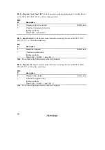
EBR2 is an 8-bit register that specifies the flash memory erase area block by block. EBR2 is
initialized to H'00 by a reset, in hardware standby mode and software standby mode, and when a
low level is input to the FWE pin. When a high level is input to the FWE pin and the SWE bit in
FLMCR1 is not set, it is initialized to bit 0. When a bit in EBR2 is set to 1, the corresponding
block can be erased. Other blocks are erase-protected. Only one bit can be set in EBR1 and EBR2
together;
do not set two or more bits at the same time. When the on-chip flash memory is disabled,
a read will return H'00, and erasing is disabled.
The flash memory block configuration is shown in table 18.5. To erase the entire flash memory,
each block must be erased in turn.
As the H8/3064F-ZTAT B-mask version does not support on-board programming modes in mode
6, EBR2 register bits cannot be set to 1 in this mode.
Summary of Contents for H8/3060
Page 10: ......
Page 16: ......
Page 114: ...66 ...
Page 132: ...84 ...
Page 144: ...96 ...
Page 170: ...122 ...
Page 212: ...164 ...
Page 268: ...220 ...
Page 332: ...284 ...
Page 396: ...348 ...
Page 494: ...446 ...
Page 698: ...650 ...
Page 748: ...700 H8 3064F ZTAT B mask version Ports 1 2 5 LED 600 Ω Figure 22 8 Sample LED Circuit ...
Page 777: ...729 H8 3062F ZTAT B mask version Ports 1 2 5 LED 600 Ω Figure 22 14 Sample LED Circuit ...
Page 810: ...762 ...
Page 994: ...946 ...


