241
8.2.8
General Registers (GRA, GRB)
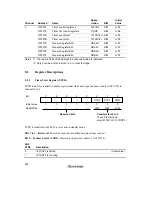
The general registers are 16-bit registers. The 16-bit timer has 6 general registers, two in each
channel.
Channel
Abbreviation
Function
0
GRA0, GRB0
Output compare/input capture register
1
GRA1, GRB1
2
GRA2, GRB2
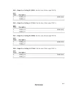
Bit
Initial value
Read/Write
14
1
R/W
12
1
R/W
10
1
R/W
8
1
R/W
6
1
R/W
0
1
R/W
4
1
R/W
2
1
R/W
15
1
R/W
13
1
R/W
11
1
R/W
9
1
R/W
7
1
R/W
1
1
R/W
5
1
R/W
3
1
R/W
A general register is a 16-bit readable/writable register that can function as either an output
compare register or an input capture register. The function is selected by settings in TIOR.
When a general register is used as an output compare register, its value is constantly compared
with the 16TCNT value. When the two values match (compare match), the IMFA or IMFB flag is
set to 1 in TISRA/TISRB. Compare match output can be selected in TIOR.
When a general register is used as an input capture register, an external input capture signal are
detected and the current 16TCNT value is stored in the general register. The corresponding IMFA
or IMFB flag in TISRA/TISRB is set to 1 at the same time. The edges of the input capture signal
are selected in TIOR.
TIOR settings are ignored in PWM mode.
General registers are linked to the CPU by an internal 16-bit bus and can be written or read by
either word access or byte access.
General registers are set as output compare registers (with no pin output) and initialized to H'FFFF
by a reset and in standby mode.
Summary of Contents for H8/3060
Page 10: ......
Page 16: ......
Page 114: ...66 ...
Page 132: ...84 ...
Page 144: ...96 ...
Page 170: ...122 ...
Page 212: ...164 ...
Page 268: ...220 ...
Page 332: ...284 ...
Page 396: ...348 ...
Page 494: ...446 ...
Page 698: ...650 ...
Page 748: ...700 H8 3064F ZTAT B mask version Ports 1 2 5 LED 600 Ω Figure 22 8 Sample LED Circuit ...
Page 777: ...729 H8 3062F ZTAT B mask version Ports 1 2 5 LED 600 Ω Figure 22 14 Sample LED Circuit ...
Page 810: ...762 ...
Page 994: ...946 ...


