223
U7001 2.5MS/s Input Unit
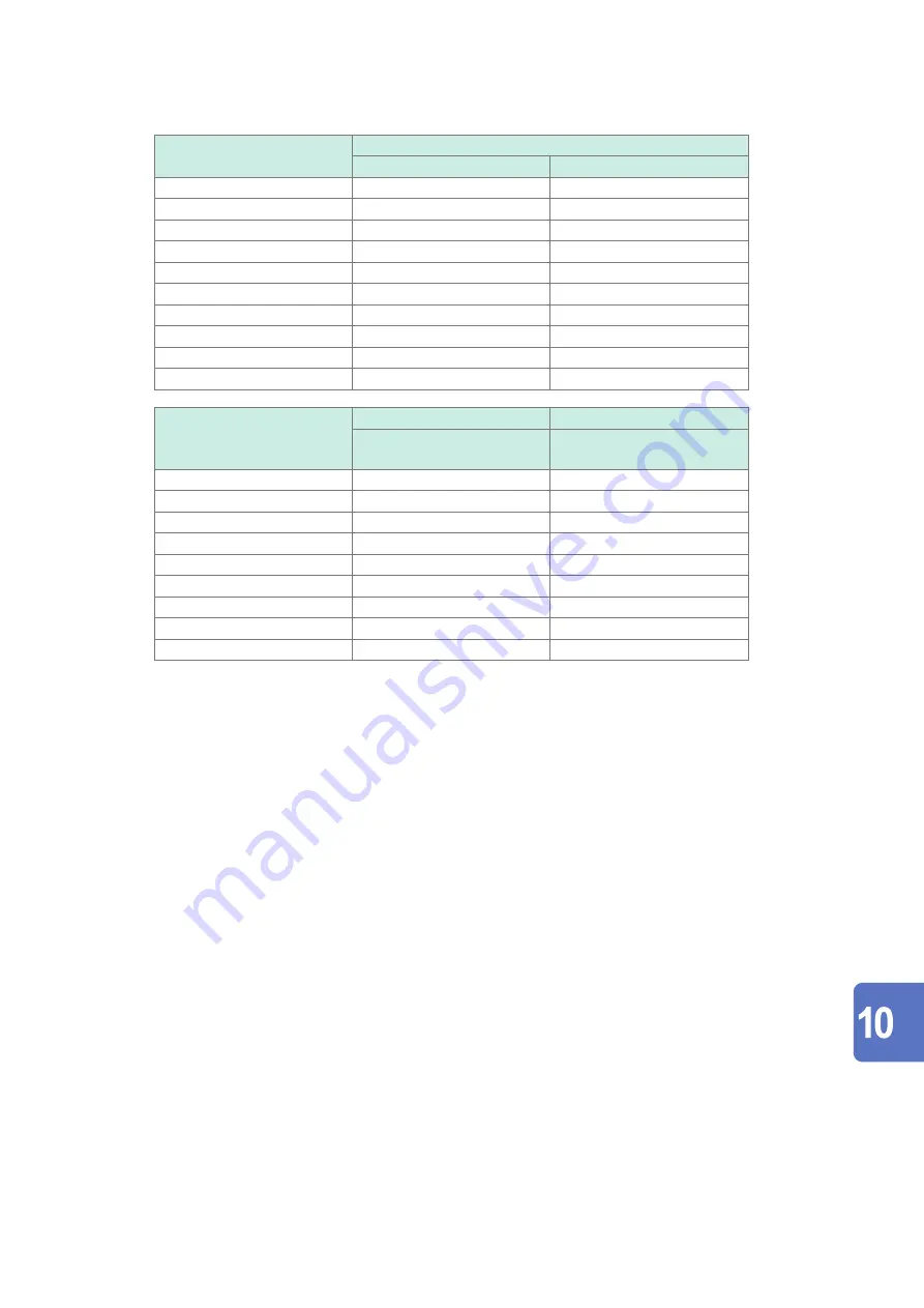
Active voltage, current, power, and power phase angle measurement accuracy
Accuracy
±
[(% of reading) + (% of range)]
Voltage (U)
Current (I)
DC
0.02% + 0.05%
0.02% + 0.05%
0.1 Hz ≤ f < 30 Hz
0.1% + 0.1 %
0.1% + 0.1%
30 Hz ≤ f < 45 Hz
0.1% + 0.1%
0.1% + 0.1%
45 Hz ≤ f ≤ 440 Hz
0.02% + 0.05%
0.02% + 0.05%
440 Hz < f ≤ 1 kHz
0.03% + 0.05%
0.03% + 0.05%
1 kHz < f ≤ 10 kHz
0.15% + 0.05%
0.15% + 0.05%
10 kHz < f ≤ 50 kHz
0.20% + 0.05%
0.20% + 0.05%
50 kHz < f ≤ 100 kHz
0.01
×
f % + 0.1%
0.01
×
f % + 0.1%
100 kHz < f ≤ 500 kHz
0.02
×
f % + 0.2%
0.02
×
f % + 0.2%
Frequency band
1 MHz (−3 dB typical)
1 MHz (−3 dB typical)
Accuracy
±
[(% of reading) + (% of range)]
Degrees
Active power (P)
Power phase angle (
φ
)
(Phase difference)
DC
0.02% + 0.05%
—
0.1 Hz ≤ f < 30 Hz
0.1% + 0.2%
±
0.05
°
30 Hz ≤ f < 45 Hz
0.1% + 0.1%
±
0.05
°
45 Hz ≤ f ≤ 440 Hz
0.02% + 0.05%
±
0.05
°
440 Hz < f ≤ 1 kHz
0.05% + 0.05%
±
0.05
°
1 kHz < f ≤ 10 kHz
0.20% + 0.05%
±
0.2
°
10 kHz < f ≤ 50 kHz
0.40% + 0.1%
±
(0.02
×
f ) degrees
50 kHz < f ≤ 100 kHz
0.01
×
f % + 0.2%
±
(0.02
×
f ) degrees
100 kHz < f ≤ 500 kHz
0.025
×
f % + 0.3%
±
(0.02
×
f ) degrees
•In the expressions listed above, the unit of
f
is kilohertz.
•
DC values of voltage and current are specified by Udc and Idc.
Frequencies other than DC are specified by U rms and I rms.
•
When U or I is selected as the synchronization source, accuracy is specified for a source input of at least 5%
of range.
•
The power phase angle is specified for a power factor of zero during 100% input.
•
For current, active power, and power phase angle, add the current sensor accuracy to the accuracy figures
listed above.
•
When 0.1 Hz ≤ f < 10 Hz, the accuracy figures for voltage, current, active power, and power phase angle are
values for reference purposes.
•
When 10 Hz ≤ f < 16 Hz, the accuracy figures for voltage, active power, and power phase angle over 220 V
are values for reference purposes.
•
When 30 kHz < f ≤ 100 kHz, the accuracy figures for voltage, active power, and power phase angle over 750 V
are reference values.
•
When 100 kHz < f ≤ 1 MHz, the accuracy figures for voltage, active power, and power phase angle over
(22000 / f [kilohertz]) volts are values for reference purposes.
•For the 6 V range, add
±
0.02% of range to voltage and active power.
•When Probe 1 is used, add
±
0.02% of range to the voltage and active power for the 1/50 range of the sensor
rating.
•When Probe 2 is used, add
±
[(0.05% of reading) + (0.2% of range)] to the current and active power and add
±
0.2
°
to the voltage phase angle for 10 kHz or more.
•The valid measurement range of the 9272-05 is between 0.5 % of full scale and 100% of full scale.
•If the input magnitude is between 100% of range (exclusive) between 110% of range (inclusive), multiply the
range error by 1.1.
•Add
±
0.01% of range per degree centigrade to the voltage DC accuracy if a change in an ambient temperature
reaches
±
1
°
C or more after zero adjustment.
When Probe 1 is used, add
±
0.01% of range per degree centigrade to the DC accuracy of the current and
active power.
When Probe 2 is used, add
±
0.05% of range per degree centigrade to the DC accuracy of the current and
active power.
Specifications
HIOKI PW8001A961-00
Summary of Contents for PW8001-01
Page 2: ...HIOKI PW8001A961 00...
Page 6: ...Contents iv HIOKI PW8001A961 00...
Page 56: ...50 Checking Connections HIOKI PW8001A961 00...
Page 120: ...114 Power Calculation Method HIOKI PW8001A961 00...
Page 162: ...156 Controlling Integration with External Signals HIOKI PW8001A961 00...
Page 236: ...230 U7005 15MS s Input Unit HIOKI PW8001A961 00...
Page 258: ...252 Index HIOKI PW8001A961 00...
Page 259: ...HIOKI PW8001A961 00...
Page 260: ...HIOKI PW8001A961 00...
Page 261: ...HIOKI PW8001A961 00...
Page 262: ...www hioki com HIOKI PW8001A961 00...


