


101
detection
the intrusion
detection
detection
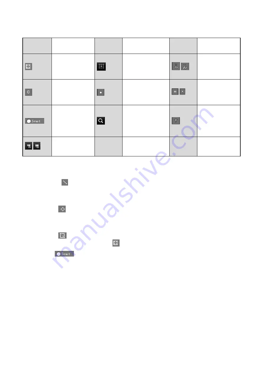
Set full screen
for motion
detection
Clear all
/
Start/Stop
clipping
File
management
for video clips
Stop playing
/
Pause playing
/Play
Smart settings
Search matched
video files
Filter video files
by setting the
target
characters
/
Show/Hide VCA
information
Step
5
Set the rules and areas for smart search of VCA event or motion event.
Line Crossing Detection
Select the
button , and click on the image to specify the start point and end point of
the line.
Intrusion Detection
Click the
button, and specify 4 points to set a quadrilateral region for intrusion
detection. Only one region can be set.
Motion Detection
Click the
button and then click and draw the mouse to set the detection area
manually. You can also click the
button to set the full screen as the detection area.
Step
6
Click
to configure the smart settings.
Skip the Non-Related Video:
The non-related video will not be played if this
function is enabled.
Play Non-Related Video at:
Set the speed to play the non-related video. Max.
8/4/2/1 are selectable.
Play Related Video at:
Set the speed to play the related video. Max. 8/4/2/1 are
selectable.
Note:
Pre-play and post-play is not available for the motion event type.
Summary of Contents for GD-RT-5008P
Page 2: ......
Page 134: ...134 Set PTZ Linking Step 8 Click OK to save the settings...


