


Switcher Control
Changing Source Tables for a Bus Link
174
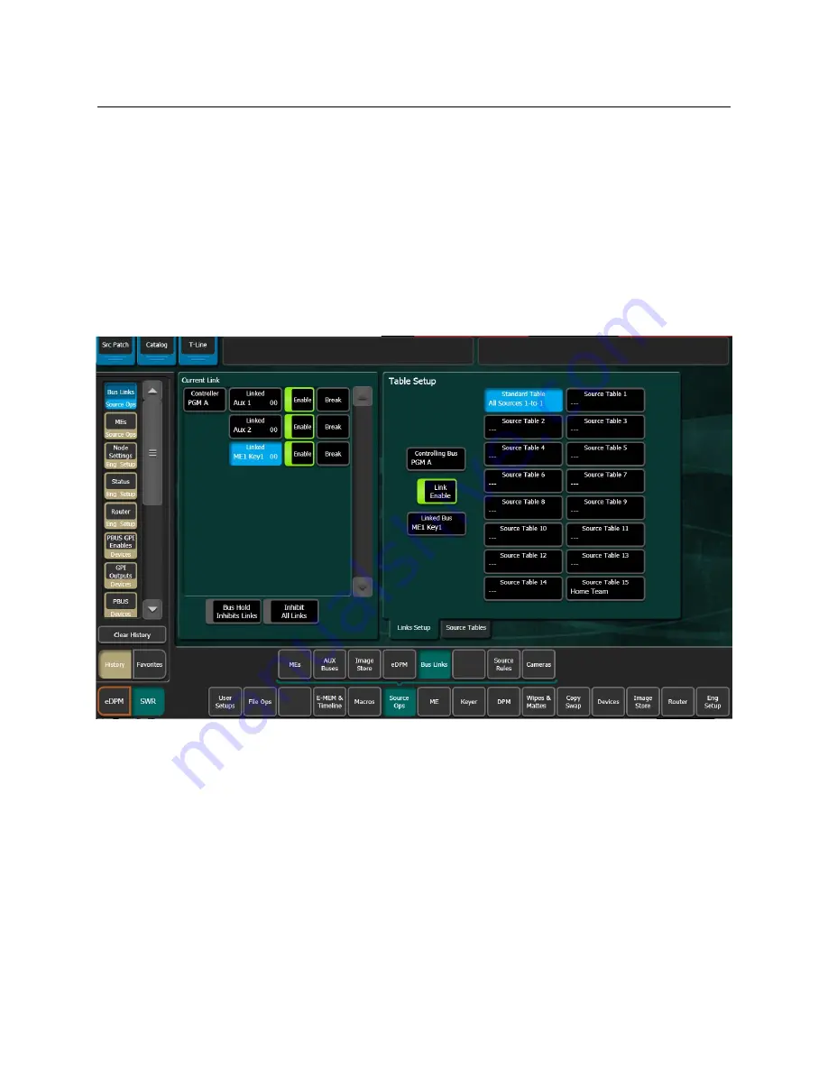
The Link Setup menu displays the newly linked buses in the Current Link pane. The link is
enabled and the Standard Source Table is selected as the default (Source Tables are grayed
out).
You can disable or break the link using the Enable/Break buttons in the Current Link pane
(the Enable button in the Table Setup pane will also enable/disable the selected link).
Creating Parallel Bus Links
Parallel Links allow the controlling bus to control more than one linked bus. In the example
menu below, PGM A is the controlling bus and Aux 1, Aux 2, and M/E1 Key1, are all linked in
parallel to PGM A.
1
Select the
Controlling Bus
data pad in the Table Setup pane; the Controlling Bus
selection menu is displayed.
2
Select the
M/E Buses
,
Aux Buses
, or
eDPM
Inputs tab and select the desired bus. The
selected bus is displayed in the
Controlling Bus
data pad (in the example menu above,
the selected bus is PGM A).
3
Select the
Linked Bus
data pad in the Table Setup pane; the Linked Bus selection menu
is displayed.
4
Select the
M/E Buses
,
Aux Buses
, or
eDPM
Inputs tab and select the desired bus. The
menu closes and returns to the Bus Links menu. The selected bus is displayed in the
Linked Bus
data pad.
5
Select the
Linked Bus
data pad again and select the next bus you wish to link to the
controlling bus.
Summary of Contents for GV KORONA
Page 16: ...Table of Contents xvi ...
Page 38: ...40 ...
Page 122: ......
Page 406: ...Kayenne Karrera GV Korona User Manual 409 ...