


GE Multilin
L30 Line Current Differential System
3-33
3 HARDWARE
3.3 PILOT CHANNEL COMMUNICATIONS
3
3.3.8 IEEE C37.94 INTERFACE
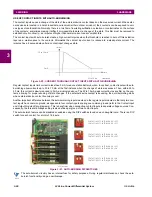
The UR-series IEEE C37.94 communication modules (modules types 76, and 77) are designed to interface with IEEE
C37.94 compliant digital multiplexers or an IEEE C37.94 compliant interface converter for use with direct input and output
applications. The IEEE C37.94 standard defines a point-to-point optical link for synchronous data between a multiplexer
and a teleprotection device. This data is typically 64 kbps, but the standard provides for speeds up to 64
n
kbps, where
n
=
1, 2,…, 12. The UR-series C37.94 communication modules are either 64 kbps (with
n
fixed at 1) for 128 kbps (with
n
fixed
at 2). The frame is a valid International Telecommunications Union (ITU-T) recommended G.704 pattern from the stand-
point of framing and data rate. The frame is 256 bits and is repeated at a frame rate of 8000 Hz, with a resultant bit rate of
2048 kbps.
The specifications for the module are as follows:.
•
IEEE standard: C37.94 for 2
64 kbps optical fiber interface (for 76 and 77 modules)
•
Fiber optic cable type: 50 mm or 62.5 mm core diameter optical fiber
•
Fiber optic mode: multi-mode
•
Fiber optic cable length: up to 2 km
•
Fiber optic connector: type ST
•
Wavelength: 830 ±40 nm
•
Connection: as per all fiber optic connections, a Tx to Rx connection is required
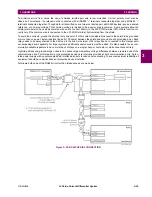
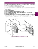
The UR-series C37.94 communication module can be connected directly to any compliant digital multiplexer that supports
the IEEE C37.94 standard as shown below.
The UR-series C37.94 communication module can be connected to the electrical interface (G.703, RS422, or X.21) of a
non-compliant digital multiplexer via an optical-to-electrical interface converter that supports the IEEE C37.94 standard, as
shown below.
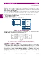
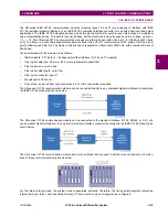
The UR-series C37.94 communication module has six (6) switches that are used to set the clock configuration. The func-
tions of these control switches are shown below.
For the internal timing mode, the system clock is generated internally. Therefore, the timing switch selection should be
internal timing for relay 1 and loop timed for relay 2. There must be only one timing source configured.
Summary of Contents for L30
Page 10: ...x L30 Line Current Differential System GE Multilin TABLE OF CONTENTS ...
Page 30: ...1 20 L30 Line Current Differential System GE Multilin 1 5 USING THE RELAY 1 GETTING STARTED 1 ...
Page 370: ...5 244 L30 Line Current Differential System GE Multilin 5 10 TESTING 5 SETTINGS 5 ...
Page 464: ...A 10 L30 Line Current Differential System GE Multilin A 1 PARAMETER LISTS APPENDIX A A ...
Page 600: ...C 30 L30 Line Current Differential System GE Multilin C 7 LOGICAL NODES APPENDIX C C ...
Page 610: ...D 10 L30 Line Current Differential System GE Multilin D 1 IEC 60870 5 104 APPENDIX D D ...
Page 622: ...E 12 L30 Line Current Differential System GE Multilin E 2 DNP POINT LISTS APPENDIX E E ...
Page 634: ...F 12 L30 Line Current Differential System GE Multilin F 3 WARRANTY APPENDIX F F ...
Page 644: ...x L30 Line Current Differential System GE Multilin INDEX ...