


GE Multilin
L30 Line Current Differential System
6-13
6 ACTUAL VALUES
6.3 METERING
6
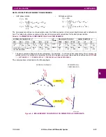
DELTA-CONNECTED INSTRUMENT TRANSFORMERS:
The zero-sequence voltage is not measurable under the Delta connection of instrument transformers and is defaulted to
zero. The table below shows an example of symmetrical components calculations for the ABC phase rotation.
*
The power system voltages are phase-referenced – for simplicity – to
VAG
and
VAB
, respectively. This, however, is a
relative matter. It is important to remember that the L30 displays are always referenced as specified under
SETTINGS
SYSTEM SETUP
POWER SYSTEM
FREQUENCY AND PHASE REFERENCE
.
The example above is illustrated in the following figure.
Figure 6–3: MEASUREMENT CONVENTION FOR SYMMETRICAL COMPONENTS
•
ABC phase rotation:
•
ACB phase rotation:
Table 6–1: SYMMETRICAL COMPONENTS CALCULATION EXAMPLE
SYSTEM VOLTAGES, SEC. V *
VT
CONN.
RELAY INPUTS, SEC. V
SYMM. COMP, SEC. V
V
AG
V
BG
V
CG
V
AB
V
BC
V
CA
F5AC
F6AC
F7AC
V
0
V
1
V
2
13.9
0°
76.2
–125°
79.7
–250°
84.9
–313°
138.3
–97°
85.4
–241°
WYE
13.9
0°
76.2
–125°
79.7
–250°
19.5
–192°
56.5
–7°
23.3
–187°
UNKNOWN (only
V
1 and
V
2
can be determined)
84.9
0°
138.3
–144°
85.4
–288°
DELTA
84.9
0°
138.3
–144°
85.4
–288°
N/A
56.5
–54°
23.3
–234°
V_0
N/A
=
V_1
1
30
–
3 3
--------------------
V
AB
aV
BC
a
2
V
CA
+
+
=
V_2
1 30
3 3
-----------------
V
AB
a
2
V
BC
aV
CA
+
+
=
V_0
N/A
=
V_1
1 30
3 3
-----------------
V
AB
a
2
V
BC
aV
CA
+
+
=
V_2
1
30
–
3 3
--------------------
V
AB
aV
BC
a
2
V
CA
+
+
=
827844A1.CDR
A
B
C
WY
E VTs
1
0
2
A
B
C
DELTA VTs
1
2
SYST
E
M VOLTAG
E
S
SYMM
E
TR
I
CAL
COMPO
NEN
TS
UR phase angle
reference
UR phase angle
reference
UR phase angle
reference
UR phase angle
reference
Summary of Contents for L30
Page 10: ...x L30 Line Current Differential System GE Multilin TABLE OF CONTENTS ...
Page 30: ...1 20 L30 Line Current Differential System GE Multilin 1 5 USING THE RELAY 1 GETTING STARTED 1 ...
Page 370: ...5 244 L30 Line Current Differential System GE Multilin 5 10 TESTING 5 SETTINGS 5 ...
Page 464: ...A 10 L30 Line Current Differential System GE Multilin A 1 PARAMETER LISTS APPENDIX A A ...
Page 600: ...C 30 L30 Line Current Differential System GE Multilin C 7 LOGICAL NODES APPENDIX C C ...
Page 610: ...D 10 L30 Line Current Differential System GE Multilin D 1 IEC 60870 5 104 APPENDIX D D ...
Page 622: ...E 12 L30 Line Current Differential System GE Multilin E 2 DNP POINT LISTS APPENDIX E E ...
Page 634: ...F 12 L30 Line Current Differential System GE Multilin F 3 WARRANTY APPENDIX F F ...
Page 644: ...x L30 Line Current Differential System GE Multilin INDEX ...