


GE Multilin
L30 Line Current Differential System
5-159
5 SETTINGS
5.6 GROUPED ELEMENTS
5
•
Transformation errors of current transformers (CTs) during double-line and three-phase faults.
•
Switch-off transients during double-line and three-phase faults.
The positive-sequence restraint must be considered when testing for pickup accuracy and response time (multiple of
pickup). The operating quantity depends on the way the test currents are injected into the relay (single-phase injection:
I
op
= (1 –
K
)
I
injected
; three-phase pure zero-sequence injection:
I
op
= 3
I
injected
).
The positive-sequence restraint is removed for low currents. If the positive-sequence current is below 0.8 pu, the restraint is
removed by changing the constant
K
to zero. This facilitates better response to high-resistance faults when the unbalance
is very small and there is no danger of excessive CT errors as the current is low.
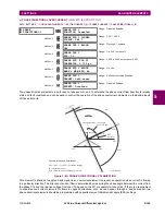
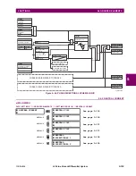
The
directional unit
uses the zero-sequence current (I_0) or ground current (IG) for fault direction discrimination and may
be programmed to use either zero-sequence voltage (“Calculated V0” or “Measured VX”), ground current (IG), or both for
polarizing. The following tables define the neutral directional overcurrent element.
where:
,
,
ECA = element characteristic angle and IG = ground current
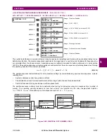
When
NEUTRAL DIR OC1 POL VOLT
is set to “Measured VX”, one-third of this voltage is used in place of V_0. The following
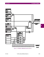
figure explains the usage of the voltage polarized directional unit of the element.
The figure below shows the voltage-polarized phase angle comparator characteristics for a phase A to ground fault, with:
•
ECA = 90° (element characteristic angle = centerline of operating characteristic)
•
FWD LA = 80° (forward limit angle = the ± angular limit with the ECA for operation)
•
REV LA = 80° (reverse limit angle = the ± angular limit with the ECA for operation)
The above bias should be taken into account when using the neutral directional overcurrent element to directionalize other
protection elements.
Table 5–22: QUANTITIES FOR "CALCULATED 3I0" CONFIGURATION
DIRECTIONAL UNIT
OVERCURRENT UNIT
POLARIZING MODE
DIRECTION
COMPARED PHASORS
Voltage
Forward
–V_0 + Z_offset
I_0
I_0
1
ECA
I
op
= 3
(|I_0| – K
|I_1|) if |I
1
| > 0.8 pu
I
op
= 3
(|I_0|) if |I
1
|
0.8 pu
Reverse
–V_0 + Z_offset
I_0
–I_0
1
ECA
Current
Forward
IG
I_0
Reverse
IG
–I_0
Dual
Forward
–V_0 + Z_offset
I_0
I_0
1
ECA
or
IG
I_0
Reverse
–V_0 + Z_offset
I_0
–I_0
1
ECA
or
IG
–I_0
Table 5–23: QUANTITIES FOR "MEASURED IG" CONFIGURATION
DIRECTIONAL UNIT
OVERCURRENT UNIT
POLARIZING MODE
DIRECTION
COMPARED PHASORS
Voltage
Forward
–V_0 + Z_offset
IG/3
IG
1
ECA
I
op
= |IG|
Reverse
–V_0 + Z_offset
IG/3
–IG
1
ECA
V_0
1
3
---
VAG VBG VCG
+
+
zero sequence voltage
=
=
I_0
1
3
---
IN
1
3
---
IA IB IC
+
+
zero sequence current
=
=
=
Summary of Contents for L30
Page 10: ...x L30 Line Current Differential System GE Multilin TABLE OF CONTENTS ...
Page 30: ...1 20 L30 Line Current Differential System GE Multilin 1 5 USING THE RELAY 1 GETTING STARTED 1 ...
Page 370: ...5 244 L30 Line Current Differential System GE Multilin 5 10 TESTING 5 SETTINGS 5 ...
Page 464: ...A 10 L30 Line Current Differential System GE Multilin A 1 PARAMETER LISTS APPENDIX A A ...
Page 600: ...C 30 L30 Line Current Differential System GE Multilin C 7 LOGICAL NODES APPENDIX C C ...
Page 610: ...D 10 L30 Line Current Differential System GE Multilin D 1 IEC 60870 5 104 APPENDIX D D ...
Page 622: ...E 12 L30 Line Current Differential System GE Multilin E 2 DNP POINT LISTS APPENDIX E E ...
Page 634: ...F 12 L30 Line Current Differential System GE Multilin F 3 WARRANTY APPENDIX F F ...
Page 644: ...x L30 Line Current Differential System GE Multilin INDEX ...