


GE Multilin
L30 Line Current Differential System
5-217
5 SETTINGS
5.7 CONTROL ELEMENTS
5
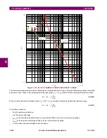
The IEC255-8 cold curve is defined as follows:
(EQ 5.23)
The IEC255-8 hot curve is defined as follows:
(EQ 5.24)
In the above equations,
•
t
op
= time to operate.
•
τ
op
= thermal protection trip time constant.
•
I
= measured overload RMS current.
•
I
p
= measured load RMS current before overload occurs.
•
k
= IEC 255-8 k-factor applied to
I
B
, defining maximum permissible current above nominal current.
•
I
B
= protected element base (nominal) current.
The reset time of the thermal overload protection element is also time delayed using following formula:
(EQ 5.25)
In the above equation,
•
τ
rst
= thermal protection trip time constant.
•
T
min
is a minimum reset time setting
t
op
op
I
2
I
2
kI
B
2
–
--------------------------
ln
=
t
op
op
I
2
I
p
2
–
I
2
kI
B
2
–
--------------------------
ln
=
t
rst
rst
kI
B
2
I
2
kI
B
2
–
-----------------------------
ln
T
min
+
=
Summary of Contents for L30
Page 10: ...x L30 Line Current Differential System GE Multilin TABLE OF CONTENTS ...
Page 30: ...1 20 L30 Line Current Differential System GE Multilin 1 5 USING THE RELAY 1 GETTING STARTED 1 ...
Page 370: ...5 244 L30 Line Current Differential System GE Multilin 5 10 TESTING 5 SETTINGS 5 ...
Page 464: ...A 10 L30 Line Current Differential System GE Multilin A 1 PARAMETER LISTS APPENDIX A A ...
Page 600: ...C 30 L30 Line Current Differential System GE Multilin C 7 LOGICAL NODES APPENDIX C C ...
Page 610: ...D 10 L30 Line Current Differential System GE Multilin D 1 IEC 60870 5 104 APPENDIX D D ...
Page 622: ...E 12 L30 Line Current Differential System GE Multilin E 2 DNP POINT LISTS APPENDIX E E ...
Page 634: ...F 12 L30 Line Current Differential System GE Multilin F 3 WARRANTY APPENDIX F F ...
Page 644: ...x L30 Line Current Differential System GE Multilin INDEX ...