5-242
L30 Line Current Differential System
GE Multilin
5.10 TESTING
5 SETTINGS
5
5.10.4 CHANNEL TESTS
PATH: SETTINGS
TESTING
CHANNEL TESTS
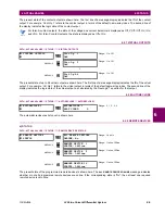
This function performs checking of the communications established by both relays.
Refer to the
Commissioning
chapter for a detailed description of using the channel tests.
5.10.5 PHASOR MEASUREMENT UNIT TEST VALUES
PATH: SETTINGS
TESTING
PMU TEST VALUES
PMU 1 TEST VALUES
CHANNEL TESTS
LOCAL LOOPBACK
MESSAGE
REMOTE LOOPBACK
LOCAL LOOPBACK
LOCAL LOOPBACK
FUNCTION: No
Range: Yes, No
MESSAGE
LOCAL LOOPBACK
CHANNEL NUMBER: 1
Range: 1, 2
REMOTE LOOPBACK
REMOTE LOOPBACK
FUNCTION: No
Range: Yes, No
MESSAGE
REMOTE LOOPBACK
CHANNEL NUMBER: 1
Range: 1, 2
PMU 1
TEST VALUES
PMU 1 TEST
FUNCTION: Disabled
Range: Enabled, Disabled
MESSAGE
PMU 1 VA TEST
MAGNITUDE: 500.00 kV
Range: 0.00 to 700.00 kV in steps of 0.01
MESSAGE
PMU 1 VA TEST
ANGLE: 0.00°
Range: –180.00 to 180.00° in steps of 0.05
MESSAGE
PMU 1 VB TEST
MAGNITUDE: 500.00 kV
Range: 0.00 to 700.00 kV in steps of 0.01
MESSAGE
PMU 1 VB TEST
ANGLE: –120.00°
Range: –180.00 to 180.00° in steps of 0.05
MESSAGE
PMU 1 VC TEST
MAGNITUDE: 500.00 kV
Range: 0.00 to 700.00 kV in steps of 0.01
MESSAGE
PMU 1 VC TEST
ANGLE: 120.00°
Range: –180.00 to 180.00° in steps of 0.05
MESSAGE
PMU 1 VX TEST
MAGNITUDE: 500.00 kV
Range: 0.00 to 700.00 kV in steps of 0.01
MESSAGE
PMU 1 VX TEST
ANGLE: 0.00°
Range: –180.00 to 180.00° in steps of 0.05
MESSAGE
PMU 1 IA TEST
MAGNITUDE: 1.000 kA
Range: 0.000 to 9.999 kA in steps of 0.001
MESSAGE
PMU 1 IA TEST
ANGLE: –10.00°
Range: –180.00 to 180.00° in steps of 0.05
Summary of Contents for L30
Page 10: ...x L30 Line Current Differential System GE Multilin TABLE OF CONTENTS ...
Page 30: ...1 20 L30 Line Current Differential System GE Multilin 1 5 USING THE RELAY 1 GETTING STARTED 1 ...
Page 370: ...5 244 L30 Line Current Differential System GE Multilin 5 10 TESTING 5 SETTINGS 5 ...
Page 464: ...A 10 L30 Line Current Differential System GE Multilin A 1 PARAMETER LISTS APPENDIX A A ...
Page 600: ...C 30 L30 Line Current Differential System GE Multilin C 7 LOGICAL NODES APPENDIX C C ...
Page 610: ...D 10 L30 Line Current Differential System GE Multilin D 1 IEC 60870 5 104 APPENDIX D D ...
Page 622: ...E 12 L30 Line Current Differential System GE Multilin E 2 DNP POINT LISTS APPENDIX E E ...
Page 634: ...F 12 L30 Line Current Differential System GE Multilin F 3 WARRANTY APPENDIX F F ...
Page 644: ...x L30 Line Current Differential System GE Multilin INDEX ...


