


5-204
L30 Line Current Differential System
GE Multilin
5.7 CONTROL ELEMENTS
5 SETTINGS
5
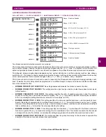
5.7.8 DIGITAL ELEMENTS
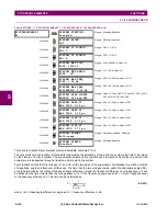
PATH: SETTINGS
CONTROL ELEMENTS
DIGITAL ELEMENTS
DIGITAL ELEMENT 1(48)
There are 48 identical digital elements available, numbered 1 to 48. A digital element can monitor any FlexLogic operand
and present a target message and/or enable events recording depending on the output operand state. The digital element
settings include a name which will be referenced in any target message, a blocking input from any selected FlexLogic oper-
and, and a timer for pickup and reset delays for the output operand.
•
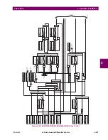
DIGITAL ELEMENT 1 INPUT:
Selects a FlexLogic operand to be monitored by the digital element.
•
DIGITAL ELEMENT 1 PICKUP DELAY:
Sets the time delay to pickup. If a pickup delay is not required, set to "0".
•
DIGITAL ELEMENT 1 RESET DELAY:
Sets the time delay to reset. If a reset delay is not required, set to “0”.
•
DIGITAL ELEMENT 1 PICKUP LED
: This setting enables or disabled the digital element pickup LED. When set to
“Disabled”, the operation of the pickup LED is blocked.
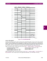
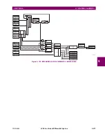
Figure 5–98: DIGITAL ELEMENT SCHEME LOGIC
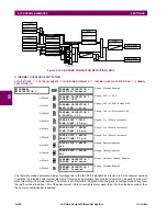
CIRCUIT MONITORING APPLICATIONS:
Some versions of the digital input modules include an active voltage monitor circuit connected across form-A contacts. The
voltage monitor circuit limits the trickle current through the output circuit (see technical specifications for form-A).
DIGITAL ELEMENT 1
DIGITAL ELEMENT 1
FUNCTION: Disabled
Range: Disabled, Enabled
MESSAGE
DIG ELEM 1 NAME:
Dig Element 1
Range: 16 alphanumeric characters
MESSAGE
DIG ELEM 1 INPUT:
Off
Range: FlexLogic operand
MESSAGE
DIG ELEM 1 PICKUP
DELAY: 0.000
s
Range: 0.000 to 999999.999 s in steps of 0.001
MESSAGE
DIG ELEM 1 RESET
DELAY: 0.000
s
Range: 0.000 to 999999.999 s in steps of 0.001
MESSAGE
DIG ELEMENT 1
PICKUP LED: Enabled
Range: Disabled, Enabled
MESSAGE
DIG ELEM 1 BLOCK:
Off
Range: FlexLogic operand
MESSAGE
DIGITAL ELEMENT 1
TARGET: Self-reset
Range: Self-reset, Latched, Disabled
MESSAGE
DIGITAL ELEMENT 1
EVENTS: Disabled
Range: Disabled, Enabled
SETTING
DIGITAL ELEMENT 01
FUNCTION:
Disabled = 0
Enabled = 1
DIGITAL ELEMENT 01
BLOCK:
Off = 0
FLEXLOGIC OPERANDS
DIG ELEM 01 DPO
DIG ELEM 01 PKP
SETTING
827042A1.VSD
DIGITAL ELEMENT 01
INPUT:
Off = 0
SETTING
INPUT = 1
RUN
t
PKP
t
RST
DIGITAL ELEMENT 01
PICKUP DELAY:
SETTINGS
DIGITAL ELEMENT 01
RESET DELAY:
AND
SETTING
DIGITAL ELEMENT 01
NAME:
DIG ELEM 01 OP
Summary of Contents for L30
Page 10: ...x L30 Line Current Differential System GE Multilin TABLE OF CONTENTS ...
Page 30: ...1 20 L30 Line Current Differential System GE Multilin 1 5 USING THE RELAY 1 GETTING STARTED 1 ...
Page 370: ...5 244 L30 Line Current Differential System GE Multilin 5 10 TESTING 5 SETTINGS 5 ...
Page 464: ...A 10 L30 Line Current Differential System GE Multilin A 1 PARAMETER LISTS APPENDIX A A ...
Page 600: ...C 30 L30 Line Current Differential System GE Multilin C 7 LOGICAL NODES APPENDIX C C ...
Page 610: ...D 10 L30 Line Current Differential System GE Multilin D 1 IEC 60870 5 104 APPENDIX D D ...
Page 622: ...E 12 L30 Line Current Differential System GE Multilin E 2 DNP POINT LISTS APPENDIX E E ...
Page 634: ...F 12 L30 Line Current Differential System GE Multilin F 3 WARRANTY APPENDIX F F ...
Page 644: ...x L30 Line Current Differential System GE Multilin INDEX ...