


GE Multilin
L30 Line Current Differential System
3-3
3 HARDWARE
3.1 DESCRIPTION
3
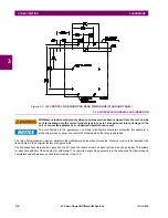
The relay must be mounted such that the faceplate sits semi-flush with the panel or switchgear door, allowing the operator
access to the keypad and the RS232 communications port. The relay is secured to the panel with the use of four screws
supplied with the relay.
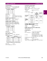
Figure 3–4: L30 VERTICAL DIMENSIONS (ENHANCED PANEL)
14.025”
7.482”
15.000”
4.000”
9.780”
11.015”
1.329”
13.560”
843809A1.CDR
Summary of Contents for L30
Page 10: ...x L30 Line Current Differential System GE Multilin TABLE OF CONTENTS ...
Page 30: ...1 20 L30 Line Current Differential System GE Multilin 1 5 USING THE RELAY 1 GETTING STARTED 1 ...
Page 370: ...5 244 L30 Line Current Differential System GE Multilin 5 10 TESTING 5 SETTINGS 5 ...
Page 464: ...A 10 L30 Line Current Differential System GE Multilin A 1 PARAMETER LISTS APPENDIX A A ...
Page 600: ...C 30 L30 Line Current Differential System GE Multilin C 7 LOGICAL NODES APPENDIX C C ...
Page 610: ...D 10 L30 Line Current Differential System GE Multilin D 1 IEC 60870 5 104 APPENDIX D D ...
Page 622: ...E 12 L30 Line Current Differential System GE Multilin E 2 DNP POINT LISTS APPENDIX E E ...
Page 634: ...F 12 L30 Line Current Differential System GE Multilin F 3 WARRANTY APPENDIX F F ...
Page 644: ...x L30 Line Current Differential System GE Multilin INDEX ...