


5-186
L30 Line Current Differential System
GE Multilin
5.7 CONTROL ELEMENTS
5 SETTINGS
5
5.7.3 SETTING GROUPS
PATH: SETTINGS
CONTROL ELEMENTS
SETTINGS GROUPS
The setting groups menu controls the activation and deactivation of up to six possible groups of settings in the
GROUPED
ELEMENTS
settings menu. The faceplate Settings In Use LEDs indicate which active group (with a non-flashing energized
LED) is in service.
The
SETTING GROUPS BLK
setting prevents the active setting group from changing when the FlexLogic parameter is set to
"On". This can be useful in applications where it is undesirable to change the settings under certain conditions, such as the
breaker being open.
The
GROUP 2 ACTIVATE ON
to
GROUP 6 ACTIVATE ON
settings select a FlexLogic operand which, when set, will make the par-
ticular setting group active for use by any grouped element. A priority scheme ensures that only one group is active at a
given time – the highest-numbered group which is activated by its
ACTIVATE ON
parameter takes priority over the lower-
numbered groups. There is no activate on setting for group 1 (the default active group), because group 1 automatically
becomes active if no other group is active.
The
SETTING GROUP 1 NAME
to
SETTING GROUP 6 NAME
settings allows to user to assign a name to each of the six settings
groups. Once programmed, this name will appear on the second line of the
GROUPED ELEMENTS
SETTING GROUP 1(6)
menu display.
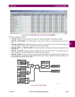
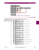
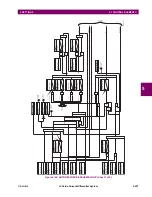
The relay can be set up via a FlexLogic equation to receive requests to activate or de-activate a particular non-default set-
tings group. The following FlexLogic equation (see the figure below) illustrates requests via remote communications (for
example,
VIRTUAL INPUT 1 ON
) or from a local contact input (for example,
CONTACT IP 1 ON
) to initiate the use of a particu-
lar settings group, and requests from several overcurrent pickup measuring elements to inhibit the use of the particular set-
tings group. The assigned
VIRTUAL OUTPUT 1
operand is used to control the “On” state of a particular settings group.
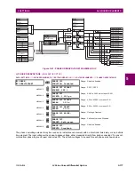
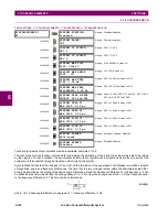
SETTING GROUPS
SETTING GROUPS
FUNCTION: Disabled
Range: Disabled, Enabled
MESSAGE
SETTING GROUPS BLK:
Off
Range: FlexLogic operand
MESSAGE
GROUP 2 ACTIVATE ON:
Off
Range: FlexLogic operand
MESSAGE
GROUP 3 ACTIVATE ON:
Off
Range: FlexLogic operand
MESSAGE
GROUP 6 ACTIVATE ON:
Off
Range: FlexLogic operand
MESSAGE
GROUP 1 NAME:
Range: up to 16 alphanumeric characters
MESSAGE
GROUP 2 NAME:
Range: up to 16 alphanumeric characters
MESSAGE
GROUP 6 NAME:
Range: up to 16 alphanumeric characters
MESSAGE
SETTING GROUP
EVENTS: Disabled
Range: Disabled, Enabled
Summary of Contents for L30
Page 10: ...x L30 Line Current Differential System GE Multilin TABLE OF CONTENTS ...
Page 30: ...1 20 L30 Line Current Differential System GE Multilin 1 5 USING THE RELAY 1 GETTING STARTED 1 ...
Page 370: ...5 244 L30 Line Current Differential System GE Multilin 5 10 TESTING 5 SETTINGS 5 ...
Page 464: ...A 10 L30 Line Current Differential System GE Multilin A 1 PARAMETER LISTS APPENDIX A A ...
Page 600: ...C 30 L30 Line Current Differential System GE Multilin C 7 LOGICAL NODES APPENDIX C C ...
Page 610: ...D 10 L30 Line Current Differential System GE Multilin D 1 IEC 60870 5 104 APPENDIX D D ...
Page 622: ...E 12 L30 Line Current Differential System GE Multilin E 2 DNP POINT LISTS APPENDIX E E ...
Page 634: ...F 12 L30 Line Current Differential System GE Multilin F 3 WARRANTY APPENDIX F F ...
Page 644: ...x L30 Line Current Differential System GE Multilin INDEX ...