9-12
L30 Line Current Differential System
GE Multilin
9.1 OVERVIEW
9 THEORY OF OPERATION
9
Depending on the 87L settings, channel asymmetry (the difference in the transmitting and receiving paths channel delay)
cannot be higher than 1 to 1.5 ms if channel asymmetry compensation is not used. However, if the relay detects asymmetry
higher than 1.5 ms, the
87L DIFF CH ASYM DET
FlexLogic™ operand is set high and the event and target are raised (if they
are enabled in the
CURRENT DIFFERENTIAL
menu) to provide an indication about potential danger.
9.1.16 ONLINE ESTIMATE OF MEASUREMENT ERRORS
GE's adaptive elliptical restraint characteristic is a good approximation to the cumulative effects of various sources of error
in determining phasors. Sources of error include power system noise, transients, inaccuracy in line charging current com-
putation, current sensor gain, phase and saturation error, clock error, and asynchronous sampling. Errors that can be con-
trolled are driven to zero by the system. For errors that cannot be controlled, all relays compute and sum the error for each
source of error for each phase. The relay computes the error caused by power system noise, CT saturation, harmonics,
and transients. These errors arise because power system currents are not always exactly sinusoidal. The intensity of these
errors varies with time; for example, growing during fault conditions, switching operations, or load variations. The system
treats these errors as a Gaussian distribution in the real and in the imaginary part of each phasor, with a standard deviation
that is estimated from the sum of the squares of the differences between the data samples and the sine function that is
used to fit them. This error has a spectrum of frequencies. Current transformer saturation is included with noise and tran-
sient error. The error for noise, harmonics, transients, and current transformer saturation is computed as follows. First, the
sum of the squares of the errors in the data samples is computed from the sum of squares information for the present
phaselet:
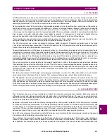
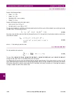
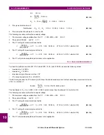
(EQ 9.28)
Then fundamental magnitude is computed as follows for the same phaselet:
(EQ 9.29)
Finally, the local adaptive restraint term is computed as follows, for each local current:
(EQ 9.30)
Another source of the measurement errors is clock synchronization error, resulting in a clock uncertainty term. The L30
algorithm accounts for two terms of synchronization error corresponding to:
•
Raw clock deviation computed from time stamps
. There are several effects that cause it to not track exactly. First, the
ping-pong algorithm inherently produces slightly different estimates of clock deviation at each terminal. Second,
because the transmission of time stamps is spread out over several packets, the clock deviation estimate is not up to
date with other information it is combined with. Channel asymmetry also contributes to this term. The clock deviation
computation is indicated in equation 8.15 as
i
. If 2 channels are used, clock deviation is computed for both channels
and then average of absolute values is computed. If GPS compensation is used, then GPS clock compensation is sub-
tracted from the clock deviation.
•
Startup error
. This term is used to estimate the initial startup transient of PFLLs. During startup conditions, a decaying
exponential is computed to simulate envelope of the error during startup
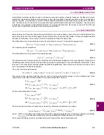
The clock uncertainty is expressed as:
(EQ 9.31)
Eventually, the local clock error is computed as:
(EQ 9.32)
The local squared adaptive restraint is computed from all local current sources (1 to 4) and is obtained as follows:
(EQ 9.33)
SumSquares
1_
A k
4
N
----
i
1_
f
_
A k p
2
p
0
N
2
1
I
1_MAG_A
I
1_RE_A
2
I
1_IM_A
2
I
1_ADA_A
2
4
N
----
SumSquares
1_
A k
I
1_MAG_A
2
clock_unc
clock_dev start_up_error
CLOCK
A
clock_unc
2
9
----------------------------------
I
LOC_RE_A
2
I
LOC_IM_A
2
I
LOC_ADA_A
2
18
I
1_ADA_A
2
I
2_ADA_A
2
I
3_ADA_A
2
I
4_ADA_A
2
I
q_ADA_A
2
CLOCK
A
Summary of Contents for L30
Page 10: ...x L30 Line Current Differential System GE Multilin TABLE OF CONTENTS ...
Page 30: ...1 20 L30 Line Current Differential System GE Multilin 1 5 USING THE RELAY 1 GETTING STARTED 1 ...
Page 370: ...5 244 L30 Line Current Differential System GE Multilin 5 10 TESTING 5 SETTINGS 5 ...
Page 464: ...A 10 L30 Line Current Differential System GE Multilin A 1 PARAMETER LISTS APPENDIX A A ...
Page 600: ...C 30 L30 Line Current Differential System GE Multilin C 7 LOGICAL NODES APPENDIX C C ...
Page 610: ...D 10 L30 Line Current Differential System GE Multilin D 1 IEC 60870 5 104 APPENDIX D D ...
Page 622: ...E 12 L30 Line Current Differential System GE Multilin E 2 DNP POINT LISTS APPENDIX E E ...
Page 634: ...F 12 L30 Line Current Differential System GE Multilin F 3 WARRANTY APPENDIX F F ...
Page 644: ...x L30 Line Current Differential System GE Multilin INDEX ...


