


5-12
L30 Line Current Differential System
GE Multilin
5.2 PRODUCT SETUP
5 SETTINGS
5
If this setting is “On” (the default setting), then remote setting access functions as normal; that is, a remote password is
required). If this setting is “Off”, then remote setting access is blocked even if the correct remote setting password is
provided. If this setting is any other FlexLogic operand, then the operand must be asserted (set as on) prior to provid-
ing the remote setting password to gain setting access.
•
ACCESS AUTH TIMEOUT
: This setting represents the timeout delay for local setting access. This setting is applicable
when the
LOCAL SETTING AUTH
setting is programmed to any operand except “On”. The state of the FlexLogic operand
is continuously monitored for an off-to-on transition. When this occurs, local access is permitted and the timer pro-
grammed with the
ACCESS AUTH TIMEOUT
setting value is started. When this timer expires, local setting access is
immediately denied. If access is permitted and an off-to-on transition of the FlexLogic operand is detected, the timeout
is restarted. The status of this timer is updated every 5 seconds.
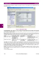
The following settings are available through the remote (EnerVista UR Setup) interface only. Select the
Settings > Product
Setup > Security
menu item to display the security settings window.
The
Remote Settings Authorization
setting is used for remote (Ethernet or RS485 interfaces) setting access supervision.
If this setting is “On” (the default setting), then remote setting access functions as normal; that is, a remote password is
required). If this setting is “Off”, then remote setting access is blocked even if the correct remote setting password is pro-
vided. If this setting is any other FlexLogic operand, then the operand must be asserted (set as on) prior to providing the
remote setting password to gain setting access.
The
Access Authorization Timeout
setting represents the timeout delay remote setting access. This setting is applicable
when the
Remote Settings Authorization
setting is programmed to any operand except “On” or “Off”. The state of the
FlexLogic operand is continuously monitored for an off-to-on transition. When this occurs, remote setting access is permit-
ted and the timer programmed with the
Access Authorization Timeout
setting value is started. When this timer expires,
remote setting access is immediately denied. If access is permitted and an off-to-on transition of the FlexLogic operand is
detected, the timeout is restarted. The status of this timer is updated every 5 seconds.
5.2.2 CYBERSENTRY SECURITY
a) SETUP
This section applies if the CyberSentry option is included with your relay.
When first using CyberSentry security, use the following procedures for set up.
First, activate and log in.
1.
Log in to the relay as Administrator by using the Value keys on the front panel to enter the default password
"ChangeMe1#". The "Lock relay" setting needs to be disabled in the
Security > Supervisory
menu. Disabling this set-
ting allows settings configuration and firmware upgrade.
2.
Enable the Supervisor role if you have a need for it.
3.
Log out the Administrator account, then log in as Observer.
Next, local or remote authentication can be used. Use local authentication to log in using the five pre-configured roles
(Administrator, Supervisor, Engineer, Operator, Observer). When using a serial connection, only local authentication is sup-
ported. For remote authentication, the RADIUS server requires configuration, as outlined here. A window pops up when try-
ing to change a setting and allows you to choose the authentication mechanism.
To use local authentication:
1.
Log in as outlined (Administrator or Supervisor, then Observer).
2.
After making any required changes, log off using the
Commands > Relay Maintenance > Security
menu.
Users
logged in through the front panel log out by logging in as None.
Summary of Contents for L30
Page 10: ...x L30 Line Current Differential System GE Multilin TABLE OF CONTENTS ...
Page 30: ...1 20 L30 Line Current Differential System GE Multilin 1 5 USING THE RELAY 1 GETTING STARTED 1 ...
Page 370: ...5 244 L30 Line Current Differential System GE Multilin 5 10 TESTING 5 SETTINGS 5 ...
Page 464: ...A 10 L30 Line Current Differential System GE Multilin A 1 PARAMETER LISTS APPENDIX A A ...
Page 600: ...C 30 L30 Line Current Differential System GE Multilin C 7 LOGICAL NODES APPENDIX C C ...
Page 610: ...D 10 L30 Line Current Differential System GE Multilin D 1 IEC 60870 5 104 APPENDIX D D ...
Page 622: ...E 12 L30 Line Current Differential System GE Multilin E 2 DNP POINT LISTS APPENDIX E E ...
Page 634: ...F 12 L30 Line Current Differential System GE Multilin F 3 WARRANTY APPENDIX F F ...
Page 644: ...x L30 Line Current Differential System GE Multilin INDEX ...