


3-24
L30 Line Current Differential System
GE Multilin
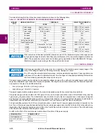
3.2 WIRING
3 HARDWARE
3
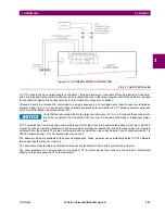
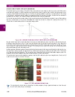
c) 100BASE-FX FIBER OPTIC PORTS
Ensure that the dust covers are installed when the fiber is not in use. Dirty or scratched connectors can lead to high
losses on a fiber link.
Observing any fiber transmitter output can injure the eye.
The fiber optic communication ports allow for fast and efficient communications between relays at 100 Mbps. Optical fiber
can be connected to the relay supporting a wavelength of 1310 nm in multi-mode.
The fiber optic port is designed such that the response times do not vary for any core that is 100 µm or less in diameter,
62.5 µm for 100 Mbps. For optical power budgeting, splices are required every 1 km for the transmitter/receiver pair. When
splicing optical fibers, the diameter and numerical aperture of each fiber must be the same.
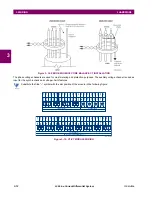
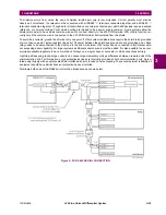
3.2.10 IRIG-B
IRIG-B is a standard time code format that allows stamping of events to be synchronized among connected devices within
1 millisecond. The IRIG time code formats are serial, width-modulated codes that can be either DC level shifted or ampli-
tude modulated (AM). Third party equipment is available for generating the IRIG-B signal; this equipment can use a GPS
satellite system to obtain the time reference so that devices at different geographic locations can be synchronized.
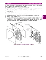
Figure 3–26: IRIG-B CONNECTION
Using an amplitude modulated receiver causes errors up to 1 ms in event time-stamping.
Using an amplitude modulated receiver also causes errors of up to 1 ms in metered synchrophasor values.
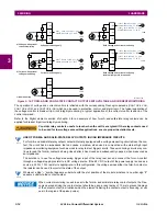
NOTE
NOTE
NOTE
Summary of Contents for L30
Page 10: ...x L30 Line Current Differential System GE Multilin TABLE OF CONTENTS ...
Page 30: ...1 20 L30 Line Current Differential System GE Multilin 1 5 USING THE RELAY 1 GETTING STARTED 1 ...
Page 370: ...5 244 L30 Line Current Differential System GE Multilin 5 10 TESTING 5 SETTINGS 5 ...
Page 464: ...A 10 L30 Line Current Differential System GE Multilin A 1 PARAMETER LISTS APPENDIX A A ...
Page 600: ...C 30 L30 Line Current Differential System GE Multilin C 7 LOGICAL NODES APPENDIX C C ...
Page 610: ...D 10 L30 Line Current Differential System GE Multilin D 1 IEC 60870 5 104 APPENDIX D D ...
Page 622: ...E 12 L30 Line Current Differential System GE Multilin E 2 DNP POINT LISTS APPENDIX E E ...
Page 634: ...F 12 L30 Line Current Differential System GE Multilin F 3 WARRANTY APPENDIX F F ...
Page 644: ...x L30 Line Current Differential System GE Multilin INDEX ...