


GE Multilin
L30 Line Current Differential System
5-213
5 SETTINGS
5.7 CONTROL ELEMENTS
5
•
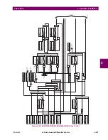
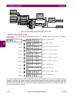
CT FAIL 3V0 INPUT PICKUP:
This setting specifies the pickup value for the 3V_0 source.
•
CT FAIL PICKUP DELAY:
This setting specifies the pickup delay of the CT failure element.
Figure 5–104: CT FAILURE DETECTOR SCHEME LOGIC
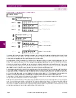
d) VT FUSE FAILURE
PATH: SETTINGS
CONTROL ELEMENTS
MONITORING ELEMENTS
VT FUSE FAILURE 1(2)
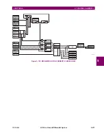
Every signal source includes a fuse failure scheme.
The VT fuse failure detector can be used to raise an alarm and/or block elements that may operate incorrectly for a full or
partial loss of AC potential caused by one or more blown fuses. Some elements that might be blocked (via the
BLOCK
input)
are distance, voltage restrained overcurrent, and directional current.
There are two classes of fuse failure that may occur:
•
Class A: loss of one or two phases.
•
Class B: loss of all three phases.
Different means of detection are required for each class. An indication of class A failures is a significant level of negative-
sequence voltage, whereas an indication of class B failures is when positive sequence current is present and there is an
insignificant amount of positive sequence voltage. These noted indications of fuse failure could also be present when faults
are present on the system, so a means of detecting faults and inhibiting fuse failure declarations during these events is pro-
vided. Once the fuse failure condition is declared, it will be sealed-in until the cause that generated it disappears.
An additional condition is introduced to inhibit a fuse failure declaration when the monitored circuit is de-energized; positive-
sequence voltage and current are both below threshold levels.
The function setting enables and disables the fuse failure feature for each source.
VT FUSE FAILURE 1
VT FUSE FAILURE 1
FUNCTION: Disabled
Range: Disabled, Enabled
MESSAGE
NEUTRAL WIRE OPEN 1
DETECTION: Disabled
Range: Disabled, Enabled
MESSAGE
NEUTRAL WIRE OPEN 1
3 HARM PKP: 0.100
0.000 to 3.000 pu in steps of 0.001
CT FAIL FUNCTION:
CT FAIL BLOCK:
CT FAIL 3IO INPUT1:
CT FAIL 3IO INPUT1 PKP:
CT FAIL 3VO INPUT:
CT FAIL 3VO INPUT:
CT FAIL 3IO INPUT2:
CT FAIL 3IO INPUT2 PKP:
CT FAIL PICKUP DELAY:
AND
OR
SETTING
Enabled=1
Disabled=0
SETTING
SETTING
SETTING
SETTING
SETTING
SETTING
SETTING
SETTING
Off=0
SRC1
RUN
3IO > PICKUP
3IO > PICKUP
3VO > PICKUP
SRC1
RUN
SRC2
RUN
FLEXLOGIC OPERANDS
CT FAIL OP
CT FAIL PKP
827048A6.CDR
0
Summary of Contents for L30
Page 10: ...x L30 Line Current Differential System GE Multilin TABLE OF CONTENTS ...
Page 30: ...1 20 L30 Line Current Differential System GE Multilin 1 5 USING THE RELAY 1 GETTING STARTED 1 ...
Page 370: ...5 244 L30 Line Current Differential System GE Multilin 5 10 TESTING 5 SETTINGS 5 ...
Page 464: ...A 10 L30 Line Current Differential System GE Multilin A 1 PARAMETER LISTS APPENDIX A A ...
Page 600: ...C 30 L30 Line Current Differential System GE Multilin C 7 LOGICAL NODES APPENDIX C C ...
Page 610: ...D 10 L30 Line Current Differential System GE Multilin D 1 IEC 60870 5 104 APPENDIX D D ...
Page 622: ...E 12 L30 Line Current Differential System GE Multilin E 2 DNP POINT LISTS APPENDIX E E ...
Page 634: ...F 12 L30 Line Current Differential System GE Multilin F 3 WARRANTY APPENDIX F F ...
Page 644: ...x L30 Line Current Differential System GE Multilin INDEX ...