


GE Multilin
L30 Line Current Differential System
5-111
5 SETTINGS
5.4 SYSTEM SETUP
5
•
PMU 1 POWER TRIGGER REACTIVE
: This setting specifies the pickup threshold for the reactive power of the
source. For single-phase power, 1 pu is a product of 1 pu voltage and 1 pu current, or the product of nominal second-
ary voltage, the VT ratio and the nominal primary current. For the three-phase power, 1 pu is three times that for a sin-
gle-phase power. The comparator applies a 3% hysteresis.
•
PMU 1 POWER TRIGGER APPARENT
: This setting specifies the pickup threshold for the apparent power of the
source. For single-phase power, 1 pu is a product of 1 pu voltage and 1 pu current, or the product of nominal second-
ary voltage, the VT ratio and the nominal primary current. For the three-phase power, 1 pu is three times that for a sin-
gle-phase power. The comparator applies a 3% hysteresis.
•
PMU 1 POWER TRIGGER PKP TIME
: This setting could be used to filter out spurious conditions and avoid unneces-
sary triggering of the recorder.
•
PMU 1 POWER TRIGGER DPO TIME
: This setting could be used to extend the trigger after the situation returned to
normal. This setting is of particular importance when using the recorder in the forced mode (recording as long as the
triggering condition is asserted).
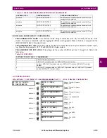
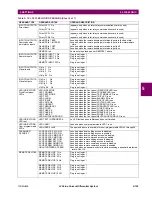
Figure 5–45: POWER TRIGGER SCHEME LOGIC
847003A1.CDR
SETTINGS
PMU 1 POWER
TRIGGER FUNCTION:
Enabled = 1
PMU 1 PWR TRIG BLK:
Off = 0
AND
SETTINGS
PMU 1 POWER TRIGGER ACTIVE:
RUN
SETTINGS
PMU 1 POWER TRIGGER PKP TIME:
PMU 1 POWER TRIGGER DPO TIME:
t
PKP
t
DPO
FLEXLOGIC OPERAND
PMU 1 POWER TRIGGER
FLEXLOGIC OPERANDS
PMU 1 FREQ TRIGGER
PMU 1 VOLT TRIGGER
PMU 1 CURR TRIGGER
PMU 1 ROCOF TRIGGER
SETTING
PMU 1 USER TRIGGER:
Off = 0
OR
FLEXLOGIC OPERAND
PMU 1 TRIGGERED
abs(P) > ACTIVE PICKUP
abs(P) > ACTIVE PICKUP
abs(P) > ACTIVE PICKUP
OR
abs(P) > 3*(ACTIVE PICKUP)
abs(Q) > REACTIVE PICKUP
abs(Q) > REACTIVE PICKUP
abs(Q) > REACTIVE PICKUP
abs(Q) > 3*(REACTIVE PICKUP)
S > APPARENT PICKUP
S > APPARENT PICKUP
S > APPARENT PICKUP
S > 3*(APPARENT PICKUP)
SETTINGS
PMU 1 SIGNAL SOURCE:
ACTIVE POWER, PA
ACTIVE POWER, PB
ACTIVE POWER, PC
3P ACTIVE POWER, P
REACTIVE POWER, QA
REACTIVE POWER, QB
REACTIVE POWER, QC
3P REACTIVE POWER, Q
APPARENT POWER, SA
APPARENT POWER, SB
APPARENT POWER, SC
3P APPARENT POWER, S
PMU 1 POWER TRIGGER REACTIVE:
PMU 1 POWER TRIGGER APPARENT:
to STAT bits of
the data frame
Summary of Contents for L30
Page 10: ...x L30 Line Current Differential System GE Multilin TABLE OF CONTENTS ...
Page 30: ...1 20 L30 Line Current Differential System GE Multilin 1 5 USING THE RELAY 1 GETTING STARTED 1 ...
Page 370: ...5 244 L30 Line Current Differential System GE Multilin 5 10 TESTING 5 SETTINGS 5 ...
Page 464: ...A 10 L30 Line Current Differential System GE Multilin A 1 PARAMETER LISTS APPENDIX A A ...
Page 600: ...C 30 L30 Line Current Differential System GE Multilin C 7 LOGICAL NODES APPENDIX C C ...
Page 610: ...D 10 L30 Line Current Differential System GE Multilin D 1 IEC 60870 5 104 APPENDIX D D ...
Page 622: ...E 12 L30 Line Current Differential System GE Multilin E 2 DNP POINT LISTS APPENDIX E E ...
Page 634: ...F 12 L30 Line Current Differential System GE Multilin F 3 WARRANTY APPENDIX F F ...
Page 644: ...x L30 Line Current Differential System GE Multilin INDEX ...