


5-140
L30 Line Current Differential System
GE Multilin
5.6 GROUPED ELEMENTS
5 SETTINGS
5
•
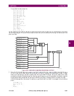
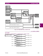
CURRENT DIFF BLOCK
: This setting selects a FlexLogic™ operand to block the operation of the current differential
element.
•
CURRENT DIFF PICKUP
: This setting is used to select current differential pickup value.
•
CURRENT DIFF CT TAP 1
and
CURRENT DIFF CT TAP 2
: These settings adapt the remote terminal 1 or 2 (commu-
nication channel) CT ratio to the local ratio if the CT ratios for the local and remote terminals are different. The setting
value is determined by CT
prim_rem
/ CT
prim_loc
for local and remote terminal CTs (where CT
prim_rem
/ CT
prim_loc
is
referred to as the CT primary rated current). Ratio matching must always be performed against the remote CT with the
maximum CT primary defined by the
CURRENT DIFF SIGNAL SOURCE 1
through
CURRENT DIFF SIGNAL SOURCE 4
settings.
See the
Current differential settings
example in the
Application of settings
chapter for additional details.
When in-zone power transformer is present, this setting should be calculated and used by taking into account the in-
zone power transformer as follows.
(EQ 5.9)
In this equation,
V
prim_rem
is primary nominal voltage of the transformer winding at the remote terminal and
V
prim_loc
is
primary nominal voltage of the transformer winding at the local terminal.
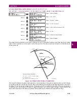
•
CURRENT DIFF RESTRAINT 1
and
CURRENT DIFF RESTRAINT 2
: These settings select the bias characteristic for
the first and second slope, respectively.
•
CURRENT DIFF BREAK PT
: This setting is used to select an intersection point between the two slopes.
•
INRUSH INHIBIT MODE
: This setting selects the mode for blocking differential protection during magnetizing inrush
conditions. Modern transformers may produce small second harmonic ratios during inrush conditions. This may result
undesired tripping of the protected line. Reducing the second harmonic inhibit threshold may jeopardize dependability
and speed of differential protection. When low, the second harmonic ratio causes problems in one phase only. This
may be utilized as a mean to ensure security by applying cross-phase blocking rather than lowering the inrush inhibit
threshold.
–
If set to “Disabled”, no inrush inhibit action is taken.
–
If set to “Per phase”, the L30 performs inrush inhibit individually in each phase.
–
If set to “2-out-of-3”, the L30 checks second harmonic level in all three phases individually. If any two phases
establish an inhibiting condition, then the remaining phase is restrained automatically.
–
If set to “Average”, the L30 first calculates the average second harmonic ratio, then applies the inrush threshold to
the calculated average.
•
INRUSH INHIBIT LEVEL
: This setting specifies the level of second harmonic component in the transformer magnetiz-
ing inrush current, above which the current differential element will be inhibited from operating. The value of the
INRUSH INHIBIT MODE
setting must be taken into account when programming this value. This setting is typically pro-
grammed as “20% f
0
“.
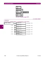
•
CURRENT DIFF GND FUNCTION
: This setting enables and disabled the 87LG neutral differential element, which may
be used to detect high-resistive faults. This element uses restrained characteristics to cope with spurious zero-
sequence current during system unbalance and signal distortions. The differential neutral current is calculated as the
vector sum of all in-zone CT input neutral currents. The restraint current is derived as the maximum of phase currents
from all terminals flowing through any individual CT, including breaker-and-a-half configurations. The 87LG neutral dif-
ferential element is blocked when the phase current at any terminal is greater than 3 pu, since the phase differential
element should operate for internal faults. To correctly derive the restraint quantity from the maximum through current
at any terminal, it is important that the 87L phase-segregated differential pickup and slope settings are equal at all ter-
minals. Refer to the
Applications of settings
chapter for additional details.
•
CURRENT DIFF GND PICKUP
: This setting specifies the pickup threshold for neutral current differential element.
•
CURRENT DIFF GND RESTRAINT
: This setting specifies the bias characteristic for the neutral current differential ele-
ment.
•
CURRENT DIFF GND DELAY
: This setting specifies the operation delay for the neutral current differential element.
Since this element is used to detect high-resistive faults where fault currents are relatively low, high-speed operation is
usually not critical. This delay will provide security against spurious neutral current during switch-off transients and
external fault clearing.
CT Tap
CT
prim_rem
V
prim_rem
CT
prim_loc
V
prim_loc
--------------------------------------------------------
for remote terminals 1 and 2, respecitvely
=
Summary of Contents for L30
Page 10: ...x L30 Line Current Differential System GE Multilin TABLE OF CONTENTS ...
Page 30: ...1 20 L30 Line Current Differential System GE Multilin 1 5 USING THE RELAY 1 GETTING STARTED 1 ...
Page 370: ...5 244 L30 Line Current Differential System GE Multilin 5 10 TESTING 5 SETTINGS 5 ...
Page 464: ...A 10 L30 Line Current Differential System GE Multilin A 1 PARAMETER LISTS APPENDIX A A ...
Page 600: ...C 30 L30 Line Current Differential System GE Multilin C 7 LOGICAL NODES APPENDIX C C ...
Page 610: ...D 10 L30 Line Current Differential System GE Multilin D 1 IEC 60870 5 104 APPENDIX D D ...
Page 622: ...E 12 L30 Line Current Differential System GE Multilin E 2 DNP POINT LISTS APPENDIX E E ...
Page 634: ...F 12 L30 Line Current Differential System GE Multilin F 3 WARRANTY APPENDIX F F ...
Page 644: ...x L30 Line Current Differential System GE Multilin INDEX ...