


17
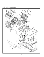
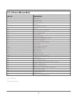
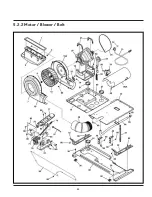
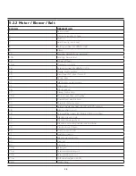
5.1.2 Motor/Blower/Belt
POS. NO
DESCRIPTION
1
Seal, air duct
3
Shield, air duct
4
Fastener, push-in
6
Duct, air
7
Seal, housing, to air duct
9
Clamp
10
Housing, blower, front w/seal
10A
Housing, blower, rear
12
Blower Wheel
15#
Thermistor, control
16
Screw, pan head, 8-18AB x 0.375
18
Cradle, motor w/idler
19
Pan ,Upper L/C, dryer, formed
22
Spring, idler
23
Idler Arm Assy, with pulley
23*#
Terminal Block, main
25
Belt, dryer, LC
26
Block, support
27
Clamp, motor mtg.
28#
Motor, dryer drive ,with pulley
33
Shield-access
38
Elbow, 90 Deg 4" Fixed
39
Screw ,#8 pan head, 10-10B x 0.500, cr/sq drive
41
Bracket, support, side
42
Bracket, marriage, dryer
44
Bracket, L mounting, cabinet rear, external
48
Pan, bottom LC dryer
50
Cover, support, LCD
51
Bushing, snap-in
80
Screw, pan head, 8-18B x 0.31
# Functional parts
* Non-Illustrated parts
Summary of Contents for FFLE3911QW
Page 1: ...Publication 5995666392 October 2015 Technical Service Manual Laundry Center ...
Page 2: ...I ...
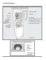
Page 9: ...8 3 Product Features ...
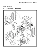
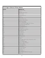
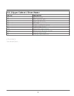
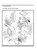
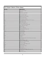
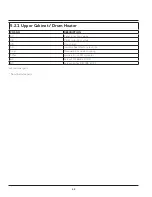
Page 14: ...13 5 1 FFLE3911QW 5 1 1 Upper Cabinet Drum Heater 5 Exploded View and List of Parts ...
Page 17: ...16 5 1 2 Motor Blower Belt ...
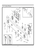
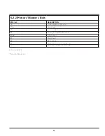
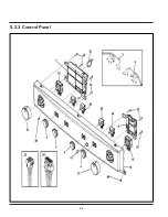
Page 19: ...18 5 1 3 Control Panel ...
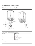
Page 21: ...20 5 2 FFLG4033QW 5 2 1 Upper Cabinet Drum Heater ...
Page 24: ...23 5 2 2 Motor Blower Belt ...
Page 27: ...26 5 2 3 Control Panel ...
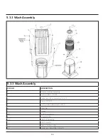
Page 32: ...31 5 3 3 Wash Assembly POS NO DESCRIPTION 14 Screw 2 PLCS 15 Lock Hub Functional parts ...
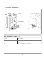
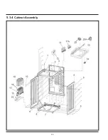
Page 33: ...32 5 3 4 Cabinet Assembly ...
Page 69: ...68 User Interface of Laundry Center FFLG4033QW ...
Page 76: ...75 8 6 Wiring Diagram FFLE3911QW Electric Dryer Model ...
Page 77: ...76 8 7 Wiring Diagram FFLG4033QW Gas Dryer Model ...
Page 78: ...77 8 8 Wiring Diagram FFLE3911QW and FFLG4033QW Washer Model ...
Page 91: ...90 Wiring Diagram FFLE3911QW Wiring Diagram FFLG4033QW ...
Page 125: ...124 ...
Page 161: ...160 ...
Page 165: ...164 ...
Page 168: ...167 ...
Page 170: ...169 ...
Page 179: ...178 ...
Page 181: ...180 ...
Page 183: ...182 ...


