


127
Checks to perform:
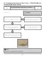
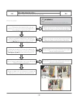
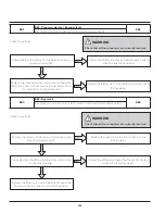
E54
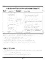
E54: Motor Centrifugal Switch 2, Heater, Thermal Limiter-2, Wiring
failure
E54
Centrifugal Switch 2 stuck open (domestic electric only), Heater open or horted
to ground, Thermal Limiter 2 open (domestic electric only), Centrifugal Switch 2
stuck closed (domestic electric only) and wiring.
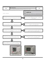
WARNING
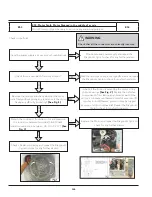
Check that all the connectors are correctly inserted
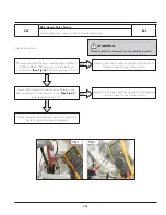
Check for the continuity between Motor Terminals (1 &
2). Is continuity there?
Replace the Motor and repeat the Diagnostic Cycle to
check for any further alarms.
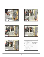
Detach the connector from the Motor and measure the
resistance between terminal 5 & 4 Check Resistance
value are in between “2.6 Ω to 3.2 Ω” ?
(See Fig.1)
NO
Replace the motor and repeat the Diagnostic Cycle to
check for any further alarms.
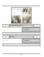
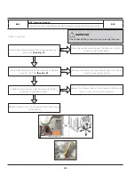
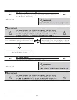
Replace the Heater and repeat the Diagnostic Cycle to
check for any further alarms.
Measure the resistance between the terminals of
Heating Element and check whether it is between 11 Ω
± 10% at room temperature (20-25°C)
(See Fig.3)
NO
Replace the Heater and repeat the Diagnostic Cycle to
check for any further alarms.
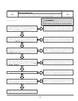
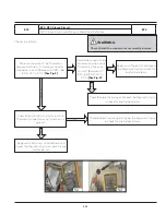
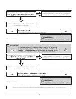
Check Inlet Thermal Limiter for continuity.Is continuity
there?
Replace the Inlet Thermal Limiter and repeat the
Diagnostic Cycle to check for any further alarms.
NO
Y
E
S
Replace the Electronic Control Board and repeat the
Diagnostic Cycle to check for any further alarms.
Y
E
S
Y
E
S
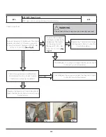
Measure between all the terminals of Heating Element
and the appliance body: Is Resistance value not “0”?
(See Fig.2)
NO
Y
E
S
YES
N
O
Summary of Contents for FFLE3911QW
Page 1: ...Publication 5995666392 October 2015 Technical Service Manual Laundry Center ...
Page 2: ...I ...
Page 9: ...8 3 Product Features ...
Page 14: ...13 5 1 FFLE3911QW 5 1 1 Upper Cabinet Drum Heater 5 Exploded View and List of Parts ...
Page 17: ...16 5 1 2 Motor Blower Belt ...
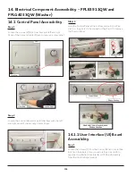
Page 19: ...18 5 1 3 Control Panel ...
Page 21: ...20 5 2 FFLG4033QW 5 2 1 Upper Cabinet Drum Heater ...
Page 24: ...23 5 2 2 Motor Blower Belt ...
Page 27: ...26 5 2 3 Control Panel ...
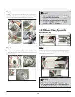
Page 32: ...31 5 3 3 Wash Assembly POS NO DESCRIPTION 14 Screw 2 PLCS 15 Lock Hub Functional parts ...
Page 33: ...32 5 3 4 Cabinet Assembly ...
Page 69: ...68 User Interface of Laundry Center FFLG4033QW ...
Page 76: ...75 8 6 Wiring Diagram FFLE3911QW Electric Dryer Model ...
Page 77: ...76 8 7 Wiring Diagram FFLG4033QW Gas Dryer Model ...
Page 78: ...77 8 8 Wiring Diagram FFLE3911QW and FFLG4033QW Washer Model ...
Page 91: ...90 Wiring Diagram FFLE3911QW Wiring Diagram FFLG4033QW ...
Page 125: ...124 ...
Page 161: ...160 ...
Page 165: ...164 ...
Page 168: ...167 ...
Page 170: ...169 ...
Page 179: ...178 ...
Page 181: ...180 ...
Page 183: ...182 ...