


150
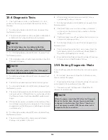
15.4 Diagnostic Tests
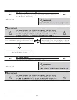
1. The Cycle Selector knob in the Normal 12 o’ clock
position is the zero position where the switches can be
checked.
2. Turn the Cycle Selector knob, (1) click clockwise from
the Normal position.
• The lid lock will activate and the hot water solenoid will
activate and the tub will be filled with hot water.
NOTE
The Clutch Actuator starts rotating to find the
“disengaged” position, and stops in this position.
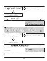
3. Turn the Cycle Selector knob, (2) clicks clockwise from
the Normal position.
• The cold water solenoid will activate and the tub will be
filled with cold water.
NOTE
The Clutch Actuator rotates to find the “disengaged”
position, and stops in this position.
4. Turn the Cycle Selector knob, (3) clicks clockwise from
the Normal position.
• The lid lock will deactivate and the lid can be opened.
5. Turn the Cycle Selector knob, (4) clicks clockwise from
the Normal position.
• The lid lock will activate and both the hot and cold water
solenoids will turn ON and fill up to a certain level. After
the Pressure Sensor has been identified, agitation will
begin.
• If the softener option is available on the machine, then
the softener solenoid will also activate and the softener
compartment will be filling up and siphoning cold water,
simultaneously.
6. Turn the Cycle Selector knob, (5) clicks clockwise from
the Normal position.
• The drum will stop and the drain pump will activate,
draining out any water in the tub.
• After draining the clutch actuator will start moving
continuously, for about 1 minute
7. Turn the Cycle Selector knob (6) clicks clockwise from
Normal position.
• The Drain Pump turns on until no water is detected
on the sensor, the clutch actuator rotates to find the
“engaged” position.
• The Drain Pump turns off just before the drum starts its
rotation to a high speed spin.
8. Turn the Cycle Selector knob (7) clicks clockwise from
Normal position.
• The control will signal the last 3 error codes. Press the
Cycle Selector knob to scroll through them. (Refer to
the section on Reading error codes).
• Press and hold the Selector knob for at least 5 seconds
in this position to clear the alarm history.
15.5 Exiting Diagnostic Mode
To exit the Diagnostics Mode, follow the instructions given
below:
1. Disconnect the power and wait for 5-8 seconds and
then reconnect the power.
2. Press and hold the Selector knob for at least 5 seconds
in the Selector Position Modes 1 to 6 CW.
3. The machine exits the Diagnostic Mode after 15
minutes of no UI activity.
NOTE
When the power is switched ON after the Diagnostic
Mode for the first time, the machine automatically
configures to the Electrical Test Mode. Therefore, it
is not necessary to switch OFF the machine, as the
Diagnostic Mode is not active.
Summary of Contents for FFLE3911QW
Page 1: ...Publication 5995666392 October 2015 Technical Service Manual Laundry Center ...
Page 2: ...I ...
Page 9: ...8 3 Product Features ...
Page 14: ...13 5 1 FFLE3911QW 5 1 1 Upper Cabinet Drum Heater 5 Exploded View and List of Parts ...
Page 17: ...16 5 1 2 Motor Blower Belt ...
Page 19: ...18 5 1 3 Control Panel ...
Page 21: ...20 5 2 FFLG4033QW 5 2 1 Upper Cabinet Drum Heater ...
Page 24: ...23 5 2 2 Motor Blower Belt ...
Page 27: ...26 5 2 3 Control Panel ...
Page 32: ...31 5 3 3 Wash Assembly POS NO DESCRIPTION 14 Screw 2 PLCS 15 Lock Hub Functional parts ...
Page 33: ...32 5 3 4 Cabinet Assembly ...
Page 69: ...68 User Interface of Laundry Center FFLG4033QW ...
Page 76: ...75 8 6 Wiring Diagram FFLE3911QW Electric Dryer Model ...
Page 77: ...76 8 7 Wiring Diagram FFLG4033QW Gas Dryer Model ...
Page 78: ...77 8 8 Wiring Diagram FFLE3911QW and FFLG4033QW Washer Model ...
Page 91: ...90 Wiring Diagram FFLE3911QW Wiring Diagram FFLG4033QW ...
Page 125: ...124 ...
Page 161: ...160 ...
Page 165: ...164 ...
Page 168: ...167 ...
Page 170: ...169 ...
Page 179: ...178 ...
Page 181: ...180 ...
Page 183: ...182 ...