


86
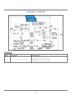
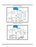
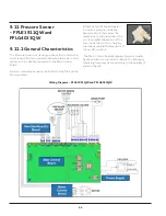
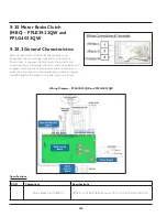
Connection Diagram - FFLE3911QW and FFLG4033QW
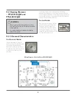
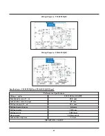
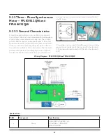
A single-phase AC current supplies the main winding that produces a pulsating magnetic field.The pulsating field could be
divided into two fields, which are rotating in opposite directions.The interaction between the fields and the current induced in
the rotor bars generates opposing torque.
The Motor Assembly is used to drive the Dryer Drum and the Blower. The motor is activated from the Electronic Control
Board through the Door Switch.
The motor is equipped with Overload Thermal Protection Tripper. This ensures that the motor is switched OFF, if any thermal
overload occurs.
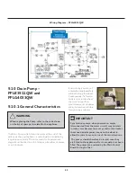
9.5 Single -Phase Induction Motor - FFLE3911QW and
FFLG4033QW (Dryer)
9.5.1 General Characteristics
Summary of Contents for FFLE3911QW
Page 1: ...Publication 5995666392 October 2015 Technical Service Manual Laundry Center ...
Page 2: ...I ...
Page 9: ...8 3 Product Features ...
Page 14: ...13 5 1 FFLE3911QW 5 1 1 Upper Cabinet Drum Heater 5 Exploded View and List of Parts ...
Page 17: ...16 5 1 2 Motor Blower Belt ...
Page 19: ...18 5 1 3 Control Panel ...
Page 21: ...20 5 2 FFLG4033QW 5 2 1 Upper Cabinet Drum Heater ...
Page 24: ...23 5 2 2 Motor Blower Belt ...
Page 27: ...26 5 2 3 Control Panel ...
Page 32: ...31 5 3 3 Wash Assembly POS NO DESCRIPTION 14 Screw 2 PLCS 15 Lock Hub Functional parts ...
Page 33: ...32 5 3 4 Cabinet Assembly ...
Page 69: ...68 User Interface of Laundry Center FFLG4033QW ...
Page 76: ...75 8 6 Wiring Diagram FFLE3911QW Electric Dryer Model ...
Page 77: ...76 8 7 Wiring Diagram FFLG4033QW Gas Dryer Model ...
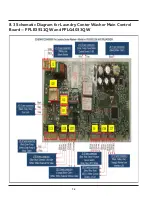
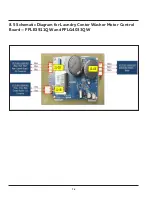
Page 78: ...77 8 8 Wiring Diagram FFLE3911QW and FFLG4033QW Washer Model ...
Page 91: ...90 Wiring Diagram FFLE3911QW Wiring Diagram FFLG4033QW ...
Page 125: ...124 ...
Page 161: ...160 ...
Page 165: ...164 ...
Page 168: ...167 ...
Page 170: ...169 ...
Page 179: ...178 ...
Page 181: ...180 ...
Page 183: ...182 ...