149
This information is intended for qualified technicians only.
CAUTION
DISCONNECT ELECTRICAL CURRENT BEFORE
SERVICING
Acronyms:
CW
- Clockwise
CCW
- Counter Clockwise
Cold Power On
- Unit plugged in for the first time
15.1 Reading Error Codes
Enter the Diagnostic Mode to read error codes (Refer to the
instructions below on how to enter this mode):
• The last recorded error code will be displayed first.
• Start/Pause/Cancel buttons should be pressed
momentarily (any time less than 1sec) to cycle through
the last 5 error codes recorded.
• E00 signifies no error code and is accompanied by no
buzzer beeps.
• Press and hold the Start/Pause/Cancel button for a
duration >= 4 seconds to clear all error codes.
Error Code Display Method -
Buzzer equipped
1. The buzzer beeps the same number of times as the first
digit of the error code (0.5 sec ON/ 0.5 sec OFF).
For example:
If the first digit is 3, the buzzer sequence will be 0.5 seconds
ON/0.5 seconds OFF/0.5 seconds ON/0.5 seconds OFF/0.5
seconds ON/0.5 seconds OFF. A, B, C, D, E, F corresponds
to the buzzer digit readings of 10, 11, 12, 13, 14, and 15,
respectively.
2. The buzzer stays silent for 2 seconds.
3. The buzzer beeps the same number of times as the
second digit of the error code (0.5 seconds ON/0.5 seconds
OFF).
4. The buzzer stays silent until the Start/Pause/Cancel
buttons are pressed momentarily to read the next error
code.
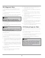
15.2 Diagnostic Mode
Use this mode under the following conditions:
• In a factory assembly line to perform a manual test of
the machine functionality (final assembly test)
• By service personell to check for faults and repair the
machine
• In the labs to check the machine functions
15.3 Entering the Diagnostic
Mode
Follow the instructions given below to enter the Diagnostic
Mode:
1. Plug the unit in or do a full control reset, which is
described in other documents. Set the Cycle Selector knob
at the 9 o’clock (presoak) position and the temperature
knob at the far left CCW position hot for LC1 (Model –
FFLE3911QW) & LC2 (Model – FFLG4033QW) and press
the Selector knob momentarily (<1 second). The other
knobs and switches do not matter.
2. Within 5 seconds, move the temperature knob to
the far right position CW and push the Selector knob
momentarily (<1 second). Move the temperature selector to
the far left CCWand push the Selector knob momentarily
(<1 second). There will be a long beep signalling the entry
into the Diagnostic/Line Test Mode. If not, start over with an
effort to perform the series of events faster or with more
precision.
15. Diagnostic System - FFLE3911QW and FFLG4033QW
(Washer)
Summary of Contents for FFLE3911QW
Page 1: ...Publication 5995666392 October 2015 Technical Service Manual Laundry Center ...
Page 2: ...I ...
Page 9: ...8 3 Product Features ...
Page 14: ...13 5 1 FFLE3911QW 5 1 1 Upper Cabinet Drum Heater 5 Exploded View and List of Parts ...
Page 17: ...16 5 1 2 Motor Blower Belt ...
Page 19: ...18 5 1 3 Control Panel ...
Page 21: ...20 5 2 FFLG4033QW 5 2 1 Upper Cabinet Drum Heater ...
Page 24: ...23 5 2 2 Motor Blower Belt ...
Page 27: ...26 5 2 3 Control Panel ...
Page 32: ...31 5 3 3 Wash Assembly POS NO DESCRIPTION 14 Screw 2 PLCS 15 Lock Hub Functional parts ...
Page 33: ...32 5 3 4 Cabinet Assembly ...
Page 69: ...68 User Interface of Laundry Center FFLG4033QW ...
Page 76: ...75 8 6 Wiring Diagram FFLE3911QW Electric Dryer Model ...
Page 77: ...76 8 7 Wiring Diagram FFLG4033QW Gas Dryer Model ...
Page 78: ...77 8 8 Wiring Diagram FFLE3911QW and FFLG4033QW Washer Model ...
Page 91: ...90 Wiring Diagram FFLE3911QW Wiring Diagram FFLG4033QW ...
Page 125: ...124 ...
Page 161: ...160 ...
Page 165: ...164 ...
Page 168: ...167 ...
Page 170: ...169 ...
Page 179: ...178 ...
Page 181: ...180 ...
Page 183: ...182 ...


