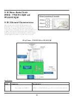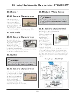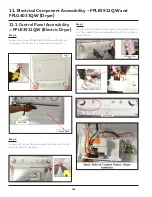
98
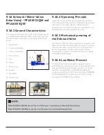
9.14 Solenoid / Water Valves
(Inlet Valve) - FFLE3911QW and
FFLG4033QW
9.14.1 General Characteristics
This component fills water into the detergent dispenser and
is controlled electrically by the Main Control Board via Triac.
The level of water in the tub is controlled by the Pressure
Sensor.
1. Water inlet
2. Solenoid valve body
3. Filter or needle trap
4. Flow reducer
5. Coil
6. Spring
7. Moving core
8. Rubber
9. Membrane
10. Water outlet
9.14.2 Operating Principle
When idle, the core pushed by a spring, keeps the central
hole of the membrane closed and so the latter hermetically
seals access to the water inlet duct. When the coil is
powered, the core is attracted, releasing the central hole of
the membrane. Consequently the valve opens.
9.14.3 Mechanical jamming of
the Solenoid Valve
The Solenoid Valve may jam or open without being actuated
(which will cause flooding if the Pressure Sensor controlling
the water level does not trip). If this occurs, the electronic
control system (which continuously monitors the flow
sensor) will lock the door, start the Drain Pump and display
an ALARM, simultaneously.
9.14.4 Low Water Pressure
The Flow Sensor may not generate a signal during the
water fill phases, even though power is being supplied to the
Solenoid Valve. This condition may result due to a closed
water tap or clogged filter on the Solenoid Valve (with
ensuing low water pressure). If this occurs, only a WARNING
will be displayed and the cycle will continue for 5 minutes,
after which an ALARM will be signalled.
NOTE
Model FFLG4033QW Washer unit has 3 coil (hot water, cold water, and softener) Solenoid Valve.
Model FFLE3911QW Washer unit has 2 coil (hot water and cold water) Solenoid Valve.
Summary of Contents for FFLE3911QW
Page 1: ...Publication 5995666392 October 2015 Technical Service Manual Laundry Center ...
Page 2: ...I ...
Page 9: ...8 3 Product Features ...
Page 14: ...13 5 1 FFLE3911QW 5 1 1 Upper Cabinet Drum Heater 5 Exploded View and List of Parts ...
Page 17: ...16 5 1 2 Motor Blower Belt ...
Page 19: ...18 5 1 3 Control Panel ...
Page 21: ...20 5 2 FFLG4033QW 5 2 1 Upper Cabinet Drum Heater ...
Page 24: ...23 5 2 2 Motor Blower Belt ...
Page 27: ...26 5 2 3 Control Panel ...
Page 32: ...31 5 3 3 Wash Assembly POS NO DESCRIPTION 14 Screw 2 PLCS 15 Lock Hub Functional parts ...
Page 33: ...32 5 3 4 Cabinet Assembly ...
Page 69: ...68 User Interface of Laundry Center FFLG4033QW ...
Page 76: ...75 8 6 Wiring Diagram FFLE3911QW Electric Dryer Model ...
Page 77: ...76 8 7 Wiring Diagram FFLG4033QW Gas Dryer Model ...
Page 78: ...77 8 8 Wiring Diagram FFLE3911QW and FFLG4033QW Washer Model ...
Page 91: ...90 Wiring Diagram FFLE3911QW Wiring Diagram FFLG4033QW ...
Page 125: ...124 ...
Page 161: ...160 ...
Page 165: ...164 ...
Page 168: ...167 ...
Page 170: ...169 ...
Page 179: ...178 ...
Page 181: ...180 ...
Page 183: ...182 ...

