


3
9.9.1 General Characteristics ........................................................................................... 91
9.10 DRAIN PUMP - FFLE3911QW AND FFLG4033QW .... 92
9.10.1 General Characteristics ....................................................................................... 92
9.11 PRESSURE SENSOR - FFLE3911QW AND
FFLG4033QW .............................................................................. 94
9.11.1 General Characteristics ....................................................................................... 94
9.12 LID / DOOR LOCK - FFLE3911QW
AND FFLG4033QW .................................................................. 96
9.12.1 General Characteristics ....................................................................................... 96
9.13 THREE - PHASE SYNCHRONOUS MOTOR -
FFLE3911QW AND FFLG4033QW ................................... 97
9.13.1 General Characteristics ....................................................................................... 97
9.14 SOLENOID / WATER VALVES (INLET VALVE) -
FFLE3911QW AND FFLG4033QW ................................... 98
9.14.1 General Characteristics ....................................................................................... 98
9.14.2 Operating principle ................................................................................................... 98
9.14.3 Mechanical jamming of the solenoid valve .................................... 98
9.14.4 Low water pressure ................................................................................................. 98
9.15 MOTOR BRAKE CLUTCH (MBC) -
FFLE3911QW AND FFLG4033QW ..................................100
9.15.1 General Characteristics ................................................................................... 100
10. HEATER (GAS) ASSEMBLY CHARACTERISTICS -
FFLG4033QW
10.1 BURNER ........................................................................................101
10.1.1 General Characteristics ................................................................................... 101
10.2 GAS VALVE ...................................................................................101
10.2.1 General Characteristics ................................................................................... 101
10.3 IGNITER .........................................................................................101
10.3.1 General Characteristics ................................................................................... 101
10.4 RADIANT / FLAME SENSOR ................................................101
10.4.1 General Characteristics ................................................................................... 101
11. ELECTRICAL COMPONENT ACCESSIBILITY -
FLE3911QW AND FFLG4033QW (DRYER)
11.1 CONTROL PANEL ACCESSIBILITY –
FFLE3911QW (ELECTRIC DRYER) ..................................102
11.1.1 Electronic Control Board Accessibility............................................ 103
11.1.2 Program Selector Accessibility ................................................................ 103
11.1.3 Temperature Selector Accessibility ..................................................... 103
11.2 CONTROL PANEL ACCESSIBILITY –
FFLG4033QW (GAS DRYER) ..............................................104
11.2.1 Electronic Control Board Accessibility............................................ 105
11.2.2 Program Selector Accessibility ................................................................ 105
11.2.3 Temperature Selector Accessibility ..................................................... 105
11.2.4 Chime Selector Accessibility ...................................................................... 106
11.3 FRONT PANEL ASSEMBLY ACCESSIBILITY ....................106
11.4 DOOR SWITCH ACCESSIBILITY ..........................................107
11.5 MOISTURE SENSOR ACCESSIBILITY ................................107
11.6 COMPONENTS ACCESSIBILITY FROM
FRONT PANEL ...........................................................................108
11.6.1 Motor / Blower Accessibility ...................................................................... 108
11.6.2 Drum Accessibility ................................................................................................. 109
11.6.3 Exhaust Thermistor Accessibility ........................................................... 111
11.6.4 Thermostat (Safety) Accessibility ........................................................... 111
11.6.5 Inlet Thermal Limiter Accessibility........................................................ 111
11.6.6 Outlet Thermal Limiter Accessibility ................................................. 112
11.7 HEATER (ELECTRIC) ASSEMBLY ACCESSIBILITY .........112
11.8 HEATER (GAS) ASSEMBLY ACCESSIBILITY .....................113
11.8.1 Radiant / Flame Sensor Accessibility ................................................. 114
11.8.2 Igniter Accessibility ................................................................................................ 115
11.8.3 Gas Valve Assembly Accessibility ........................................................... 115
12. DIAGNOSTIC SYSTEM –
FFLE3911QW AND FFLG4033QW (DRYER)
13. TROUBLESHOOTING BASED ON ALARM CODES –
FFLE3911QW AND FFLG4033QW
(DRYER MODEL)
E31: CONTACT SENSOR (MOISTURE SENSOR)
FREQUENCY IS TOO HIGH / LOW ...................................121
E41: DOOR OPEN ...............................................................................122
E51: MOTOR RELAY FAILURE ........................................................123
E52: MOTOR RELAY STUCK CLOSE ............................................125
E53: MOTOR FAULT- MOTOR STOPPED IN
THE MIDDLE OF A CYCLE .....................................................126
E54: MOTOR CENTRIFUGAL SWITCH 2, HEATER,
THERMAL LIMITER-2, WIRING FAILURE .......................127
E55: MOTOR SENSING FAILURE ON MAIN BOARD .............128
E56: BELT FAULT ..................................................................................128
E61: HEATER RELAY FAILURE ........................................................129
E62: HEATING TIMEOUT ..................................................................130
E65: HIGH LIMIT THERMOSTAT TRIP COUNT
IS TOO HIGH ...............................................................................131
E67: HEATER SENSING FAILURE ..................................................131
E71: NTC OPEN CIRCUIT .................................................................132
E72: NTC CLOSED CIRCUIT ............................................................133
E81: PROGRAM SELECTOR / ENCODER FAULT ....................134
E82: KEY STUCK ..................................................................................134
E93: SOFTWARE CONFIGURATION ERROR ...........................135
E94: SOFTWARE CONFIGURATION ERROR ...........................135
E97: SOFTWARE CONFIGURATION ...........................................135
EA1: MAIN SUPPLY FREQUENCY OUT OF RANGE ..............136
EA2: VOLTAGE TOO HIGH ...............................................................136
EA3: VOLTAGE TOO LOW ................................................................137
EA5: LINE AMPLITUDE SENSING
FAILURE ON MAIN BOARD ..................................................137
14. ELECTRICAL COMPONENT ACCESSIBILITY -
FFLE3911QW AND FFLG4033QW (WASHER)
14.1 CONTROL PANEL ACCESSIBILITY .....................................138
14.1.1 User Interface (UI) Board Accessibility ............................................ 138
14.1.2 Program Selector Accessibility ................................................................ 139
14.1.3 Temperature Selector Accessibility ..................................................... 139
14.1.4 Fabric Softener Accessibility.........................................................................140
Summary of Contents for FFLE3911QW
Page 1: ...Publication 5995666392 October 2015 Technical Service Manual Laundry Center ...
Page 2: ...I ...
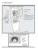
Page 9: ...8 3 Product Features ...
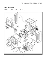
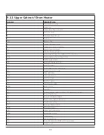
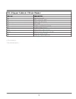
Page 14: ...13 5 1 FFLE3911QW 5 1 1 Upper Cabinet Drum Heater 5 Exploded View and List of Parts ...
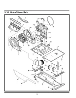
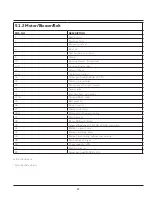
Page 17: ...16 5 1 2 Motor Blower Belt ...
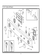
Page 19: ...18 5 1 3 Control Panel ...
Page 21: ...20 5 2 FFLG4033QW 5 2 1 Upper Cabinet Drum Heater ...
Page 24: ...23 5 2 2 Motor Blower Belt ...
Page 27: ...26 5 2 3 Control Panel ...
Page 32: ...31 5 3 3 Wash Assembly POS NO DESCRIPTION 14 Screw 2 PLCS 15 Lock Hub Functional parts ...
Page 33: ...32 5 3 4 Cabinet Assembly ...
Page 69: ...68 User Interface of Laundry Center FFLG4033QW ...
Page 76: ...75 8 6 Wiring Diagram FFLE3911QW Electric Dryer Model ...
Page 77: ...76 8 7 Wiring Diagram FFLG4033QW Gas Dryer Model ...
Page 78: ...77 8 8 Wiring Diagram FFLE3911QW and FFLG4033QW Washer Model ...
Page 91: ...90 Wiring Diagram FFLE3911QW Wiring Diagram FFLG4033QW ...
Page 125: ...124 ...
Page 161: ...160 ...
Page 165: ...164 ...
Page 168: ...167 ...
Page 170: ...169 ...
Page 179: ...178 ...
Page 181: ...180 ...
Page 183: ...182 ...


