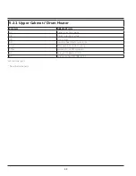


36
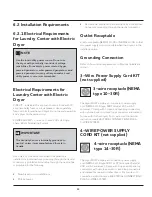
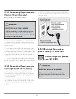
6.2.2 Electrical Requirements for
Laundry Center with Gas Dryer
CIRCUIT - Individual,
properly polarized and
grounded 15 amp. branch
circuit fused with 15 amp.
time delay fuse or circuit
breaker.
POWER SUPPLY- 2-wire,
with ground, 120 volt,
single phase, 60 Hz,
Alternating Current.
POWER SUPPLY CORD - The dryer is equipped with a 120
volt 3-wire power cord.
GROUNDING CONNECTION - See “Grounding
requirements” in Electrical Installation Section.
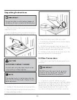
6.2.3 Gas Supply Requirements
1. Ensure that the installation process MUST conform
with local codes, or in the absence of local codes, with the
National Fuel Gas Code, ANSI Z223.1 (latest edition).
2. Ensure that the gas supply line should be 1 / 2 inch
(1.27cm) pipe.
3. Use a flexible metal tubing to connect your dryer to
the gas supply line, if codes allow. The tubing MUST be
constructed of stainless steel or plastic - coated brass.
4. Install an individual shut off valve in the gas supply line
in accordance with the B149.1, Natural Gas and Propane
Installation Code.
5. Install an 1 / 8 inch (0.32 cm) N.P.T. plugged tapping,
accessible for test gauge connection, is installed immediately
upstream of the gas supply connection to the dryer.
6. Disconnect the dryer from the gas supply piping system
during any pressure testing of the gas supply piping system
at test pressures in excess of 1 / 2 psig (3.45 kPa).
7. Isolate the dryer from the gas supply piping system
during any pressure testing of the gas supply piping system
at test pressures equal to or less than 1 / 2 psig (3.45 kPa).
8. Connections for the gas supply MUST comply with the
Standard for Connectors for Gas Appliances, ANSI Z21.24.
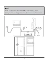
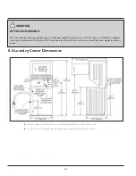
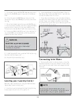
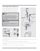
6.2.4 Water Supply
Requirements
Install hot and cold water faucets within 42 inches (107 cm)
of your washer’s water inlet. The faucets MUST be 3 / 4 inch
(1.9 cm) with threading for laundry hose connection. Water
pressure MUST be between 10 psi (0.69 bars) and 120 psi
(8.27 bars). Pressure difference between hot and cold water
cannot be more than 10 psi. The water department can
advise you on the water pressure.
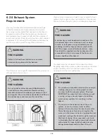
6.2.5 Drain System
Requirements
• The drain system requirements are as follows:
• Drain capable of eliminating 17 gals (64.3 L) per minute.
• A standpipe diameter of 1-1/4 inches (3.18 cm)
minimum.
The standpipe height above the floor should be:
— Minimum height: 33 inches (84 cm)
— Maximum height: 96 inches (244 cm)
NOTE
Laundry Centers manufactured for sale in Canada
have factory-installed, 4-wire power supply cord
(NEMA 14-30R).
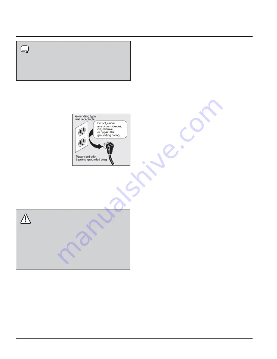
WARNING
EXPLOSION HAZARD
Uncoated copper tubing will corrode when subjected
to natural gas, causing gas leakages. Use ONLY black
iron, stainless steel or plastic coated brass piping for
gas supply.
Summary of Contents for FFLE3911QW
Page 1: ...Publication 5995666392 October 2015 Technical Service Manual Laundry Center ...
Page 2: ...I ...
Page 9: ...8 3 Product Features ...
Page 14: ...13 5 1 FFLE3911QW 5 1 1 Upper Cabinet Drum Heater 5 Exploded View and List of Parts ...
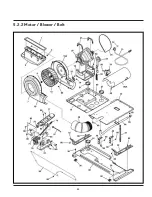
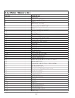
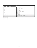
Page 17: ...16 5 1 2 Motor Blower Belt ...
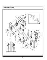
Page 19: ...18 5 1 3 Control Panel ...
Page 21: ...20 5 2 FFLG4033QW 5 2 1 Upper Cabinet Drum Heater ...
Page 24: ...23 5 2 2 Motor Blower Belt ...
Page 27: ...26 5 2 3 Control Panel ...
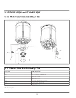
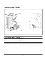
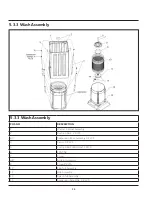
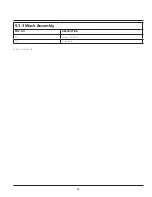
Page 32: ...31 5 3 3 Wash Assembly POS NO DESCRIPTION 14 Screw 2 PLCS 15 Lock Hub Functional parts ...
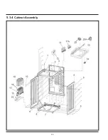
Page 33: ...32 5 3 4 Cabinet Assembly ...
Page 69: ...68 User Interface of Laundry Center FFLG4033QW ...
Page 76: ...75 8 6 Wiring Diagram FFLE3911QW Electric Dryer Model ...
Page 77: ...76 8 7 Wiring Diagram FFLG4033QW Gas Dryer Model ...
Page 78: ...77 8 8 Wiring Diagram FFLE3911QW and FFLG4033QW Washer Model ...
Page 91: ...90 Wiring Diagram FFLE3911QW Wiring Diagram FFLG4033QW ...
Page 125: ...124 ...
Page 161: ...160 ...
Page 165: ...164 ...
Page 168: ...167 ...
Page 170: ...169 ...
Page 179: ...178 ...
Page 181: ...180 ...
Page 183: ...182 ...


