


118
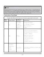
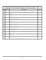
Diagnostic Mode (All Cycle Selector positions in this table are going clockwise from Position-0)
Selector
Position
Encoder Positions
Test/Activated
Components
Operator Check
3
A) Temp Selector: Low
B) Rocker Switches
(select models): OFF
C) Dryness Level
Selector Positions
(select models):
1 - Max/High /Extra
Dry
2- High/Normal /More
Dry
3- Normal/Low/
Normal Dry
4- Low/Damp Dry
5-Damp
Contact Sensor
(Operator will only
be able to verify “1- “
for models that have
contact sensors but
no Dryness Level
Selector)
Contact Sensor Shorted: Beeper/LED Active
Contact Sensor Open: Beeper/LED Inactive
Dryness Level Selector Position:
1- Continuous Beep—655s On-0.25s Off-
Repeats—255 Times**; Same LED Pattern.
2- 1s On-3s Off- Repeats—255 Times**; Same LED
Pattern.
3- 1s On-1s Off-1s On-3s Off- Repeats— 255
Times**; Same LED Pattern.
4- 1s On-1s Off-1s On-1s Off-1s On-3s Off—
Repeats—255 Times**;Same LED Pattern.
5- 1s On-1s Off-1s On-1s Off-1s On-1s Off-1s On-
3s Off—Repeats—255 Times**; Same LED Pattern.
4
N/A
Error code display
Check error codes
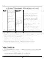
** The repeating sequence will time out automatically after 255 times. To refresh the counter, change the cycle selector to a
different position, while still in Diagnostic Mode and come back to the initially selected position.
7. Follow the instructions below to exit the Diagnostic Mode:
a. Unplug the power cord, wait for 5-8 seconds, and then reconnect the power cord.
b. Perform a Full Control Reset, by Pressing and Holding the Cycle Selector knob for 6 seconds.
c. Automatically exit the Diagnostic Mode if there is no change in the User Interface for 30 minutes.
Reading Error Codes
1. Error Codes can be viewed only in the Diagnostic Mode and when the Cycle Selector is in Position – 4 (See Diagnostic
Modetable).
2. The error code recorded last will be displayed first.
3. Press the Start/Pause button to cycle through/view the last 5 error codes recorded.
4. Press and Hold the Cycle Selector Knob for 3 seconds to clear the error code(s).
Summary of Contents for FFLE3911QW
Page 1: ...Publication 5995666392 October 2015 Technical Service Manual Laundry Center ...
Page 2: ...I ...
Page 9: ...8 3 Product Features ...
Page 14: ...13 5 1 FFLE3911QW 5 1 1 Upper Cabinet Drum Heater 5 Exploded View and List of Parts ...
Page 17: ...16 5 1 2 Motor Blower Belt ...
Page 19: ...18 5 1 3 Control Panel ...
Page 21: ...20 5 2 FFLG4033QW 5 2 1 Upper Cabinet Drum Heater ...
Page 24: ...23 5 2 2 Motor Blower Belt ...
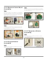
Page 27: ...26 5 2 3 Control Panel ...
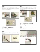
Page 32: ...31 5 3 3 Wash Assembly POS NO DESCRIPTION 14 Screw 2 PLCS 15 Lock Hub Functional parts ...
Page 33: ...32 5 3 4 Cabinet Assembly ...
Page 69: ...68 User Interface of Laundry Center FFLG4033QW ...
Page 76: ...75 8 6 Wiring Diagram FFLE3911QW Electric Dryer Model ...
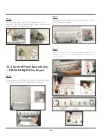
Page 77: ...76 8 7 Wiring Diagram FFLG4033QW Gas Dryer Model ...
Page 78: ...77 8 8 Wiring Diagram FFLE3911QW and FFLG4033QW Washer Model ...
Page 91: ...90 Wiring Diagram FFLE3911QW Wiring Diagram FFLG4033QW ...
Page 125: ...124 ...
Page 161: ...160 ...
Page 165: ...164 ...
Page 168: ...167 ...
Page 170: ...169 ...
Page 179: ...178 ...
Page 181: ...180 ...
Page 183: ...182 ...