


45
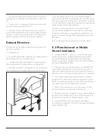
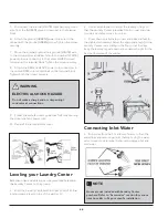
1. Turn OFF the power supply to the outlet.
2. Remove the screw securing the terminal block access
cover in the lower corner on the back of the dryer.
3. Install a UL-approved strain relief according to the
power cord / strain relief manufacturer’s instructions
in the power cord entry hole below the access panel.
Simultaneously, the strain relief should be loosely in place.
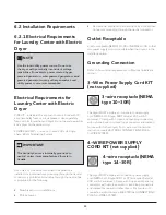
4. Thread an UNPLUGGED, UL-approved, 30 amp. power
cord, NEMA 10-30 type SRDT, through the strain relief.
5. Attach the power cord neutral (center wire) conductor
to the SILVER colored center terminal on the terminal block.
Tighten the screw securely.
6. Attach the outer conductors of the two remaining
power cords to the outer BRASS colored terminals on the
terminal block. Tighten both screws securely.
7. Follow the manufacturer’s guidelines for firmly securing
the strain relief and power cord.
8. Reinstall the terminal block cover.
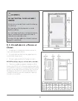
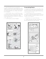
6.5.4 Electrical Connection
(non-Canada) - 4 wire cord
4-wire receptacle (NEMA
type 14-30R)
1. Turn OFF the power supply to outlet.
2. Remove the screw securing the terminal block access
cover in the lower corner on the back of the dryer.
3. Install a UL-approved strain relief according to the
power cord / strain relief manufacturer’s instructions in the
power cord entry hole below the access panel. At this time,
the strain relief should be loosely in place.
4. Thread an UNPLUGGED, UL-approved strain relief, 30
amp. power cord, NEMA 14-30 type ST or SRDT, through
the strain relief.
WARNING
ELECTRICAL SHOCK HAZARD
Do not make a sharp bend or crimp wiring /
conductor at connections.
WARNING
ELECTRICAL SHOCK HAZARD
Failure to disconnect power source before servicing
could result in personal injury or even death.
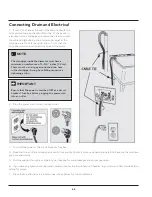
IMPORTANT
To move a dryer from a 4-wire system and to install
it in a 3-wire system, move the internal ground from
the center terminal back to the GREEN screw next
to the terminal block.
NOTE
If a terminal screw falls during cord installation, it
can be retrieved in the terminal screw recovery slot
below the access panel.
Summary of Contents for FFLE3911QW
Page 1: ...Publication 5995666392 October 2015 Technical Service Manual Laundry Center ...
Page 2: ...I ...
Page 9: ...8 3 Product Features ...
Page 14: ...13 5 1 FFLE3911QW 5 1 1 Upper Cabinet Drum Heater 5 Exploded View and List of Parts ...
Page 17: ...16 5 1 2 Motor Blower Belt ...
Page 19: ...18 5 1 3 Control Panel ...
Page 21: ...20 5 2 FFLG4033QW 5 2 1 Upper Cabinet Drum Heater ...
Page 24: ...23 5 2 2 Motor Blower Belt ...
Page 27: ...26 5 2 3 Control Panel ...
Page 32: ...31 5 3 3 Wash Assembly POS NO DESCRIPTION 14 Screw 2 PLCS 15 Lock Hub Functional parts ...
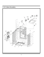
Page 33: ...32 5 3 4 Cabinet Assembly ...
Page 69: ...68 User Interface of Laundry Center FFLG4033QW ...
Page 76: ...75 8 6 Wiring Diagram FFLE3911QW Electric Dryer Model ...
Page 77: ...76 8 7 Wiring Diagram FFLG4033QW Gas Dryer Model ...
Page 78: ...77 8 8 Wiring Diagram FFLE3911QW and FFLG4033QW Washer Model ...
Page 91: ...90 Wiring Diagram FFLE3911QW Wiring Diagram FFLG4033QW ...
Page 125: ...124 ...
Page 161: ...160 ...
Page 165: ...164 ...
Page 168: ...167 ...
Page 170: ...169 ...
Page 179: ...178 ...
Page 181: ...180 ...
Page 183: ...182 ...