


168
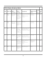
E35
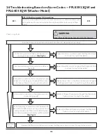
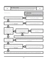
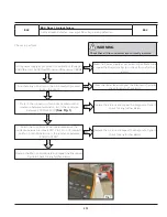
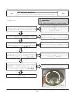
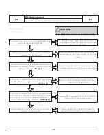
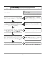
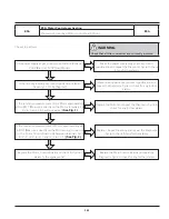
E35: Water Overload
E35
Pressure sensor hose blocked, Water inlet valve.
Checks to perform:
WARNING
Check that all the connectors are correctly inserted.
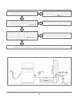
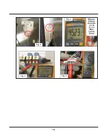
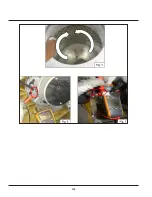
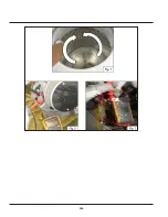
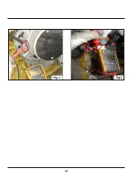
Is the air tube connected properly (check also for kinking
and leaking) ? (Disconnect the tubes and blow into them to
make sure the system is unobstructed)
(See Fig. 1)
Replace or Repair the air tube and repeat the Diagnostic
Cycle to check for any further alarms.
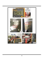
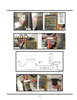
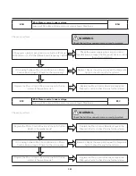
Is the resistance measurement of the Solenoid Valve
approximately 1375Ω ± 10%? (Measure it directly on the
Solenoid Valve terminals without wiring)
(See Fig. 3)
Replace the Solenoid Valve and repeat the Diagnostic
Cycle to check for any further alarms.
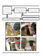
Reconnect the connector and measure approximately
1375Ω ± 10% on the Solenoid Valve wiring connector on
the circuit board side between terminals J20-1 & J20-3,
J18-1& J18-3 and J18-4 & J18-6
(See Fig. 4)
. Is the
Solenoid Valve wiring ok?
Replace / Repair the wiring and repeat the Diagnostic
Cycle to check for any further alarms.
Replace the Main Control Board and repeat the Diagnostic
Cycle to check for any further alarms.
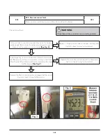
Is the frequency of Pressure Sensor between 45 Hz to 45.5
Hz? (Measure it on the pressure sensor wiring connector at
Main Control Board when machine is powered with empty
tub (No water))
(See Fig.2)
Replace Pressure Sensor and repeat the Diagnostic
Cycle to check for any further alarms.
NO
NO
NO
NO
Y
E
S
Y
E
S
Y
E
S
Y
E
S
Summary of Contents for FFLE3911QW
Page 1: ...Publication 5995666392 October 2015 Technical Service Manual Laundry Center ...
Page 2: ...I ...
Page 9: ...8 3 Product Features ...
Page 14: ...13 5 1 FFLE3911QW 5 1 1 Upper Cabinet Drum Heater 5 Exploded View and List of Parts ...
Page 17: ...16 5 1 2 Motor Blower Belt ...
Page 19: ...18 5 1 3 Control Panel ...
Page 21: ...20 5 2 FFLG4033QW 5 2 1 Upper Cabinet Drum Heater ...
Page 24: ...23 5 2 2 Motor Blower Belt ...
Page 27: ...26 5 2 3 Control Panel ...
Page 32: ...31 5 3 3 Wash Assembly POS NO DESCRIPTION 14 Screw 2 PLCS 15 Lock Hub Functional parts ...
Page 33: ...32 5 3 4 Cabinet Assembly ...
Page 69: ...68 User Interface of Laundry Center FFLG4033QW ...
Page 76: ...75 8 6 Wiring Diagram FFLE3911QW Electric Dryer Model ...
Page 77: ...76 8 7 Wiring Diagram FFLG4033QW Gas Dryer Model ...
Page 78: ...77 8 8 Wiring Diagram FFLE3911QW and FFLG4033QW Washer Model ...
Page 91: ...90 Wiring Diagram FFLE3911QW Wiring Diagram FFLG4033QW ...
Page 125: ...124 ...
Page 161: ...160 ...
Page 165: ...164 ...
Page 168: ...167 ...
Page 170: ...169 ...
Page 179: ...178 ...
Page 181: ...180 ...
Page 183: ...182 ...