


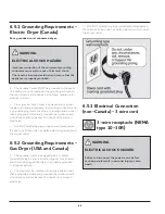


39
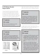
In installations where the exhaust system is not described in
the charts, use the following methods to determine if the
exhaust system is acceptable:
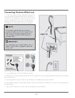
1. Connect an inclined or digital manometer between the
dryer and the point the exhaust connects to the dryer.
2. Set the dryer timer and temperature to air fluff (cool
down) and start the dryer.
3. Read the measurement on the manometer.
4. The system back pressure MUST NOT be higher than
0.6 inch of water column. If the system back pressure is less
than 0.6 inch of water column, the system is acceptable. If
the manometer reading is higher than 0.6 inch of water
column, the system is too restrictive and the installation is
unacceptable
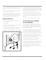
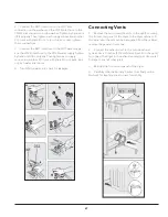
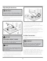
Although vertical orientation of the exhaust system is
acceptable, certain extenuating circumstances could affect
the performance of the dryer:
1. Use the rigid metal duct work only.
2. Venting vertically through a roof may expose the
exhaust system to down drafts causing an increase in vent
restriction.
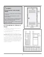
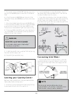
WARNING
FIRE HAZARD
Exceeding the length of duct pipe or number of
elbows as seen in “MAXIMUM LENGTH” charts can
cause an accumulation of lint in the exhaust system.
Plugging the system could create a fire hazard, and
increase the time of drying.
WARNING
FIRE HAZARD
Do not install flexible plastic or flexible foil venting
material.
If installing semi-rigid venting, do not exceed 8 ft.
(2.4 m) duct length.
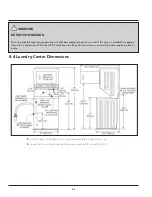
WARNING
FIRE HAZARD
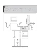
Do not install the Laundry Center where gasoline
or other flammables are kept or stored. If the dryer
is installed in a garage, it must be a minimum of 18
inches (45.7 cm) above the floor. Failure to do so can
result in death, explosion, fire or burns.
Summary of Contents for FFLE3911QW
Page 1: ...Publication 5995666392 October 2015 Technical Service Manual Laundry Center ...
Page 2: ...I ...
Page 9: ...8 3 Product Features ...
Page 14: ...13 5 1 FFLE3911QW 5 1 1 Upper Cabinet Drum Heater 5 Exploded View and List of Parts ...
Page 17: ...16 5 1 2 Motor Blower Belt ...
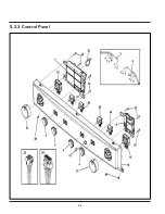
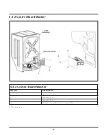
Page 19: ...18 5 1 3 Control Panel ...
Page 21: ...20 5 2 FFLG4033QW 5 2 1 Upper Cabinet Drum Heater ...
Page 24: ...23 5 2 2 Motor Blower Belt ...
Page 27: ...26 5 2 3 Control Panel ...
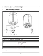
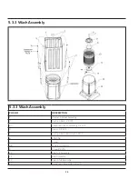
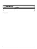
Page 32: ...31 5 3 3 Wash Assembly POS NO DESCRIPTION 14 Screw 2 PLCS 15 Lock Hub Functional parts ...
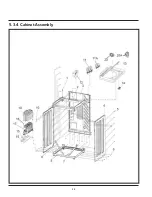
Page 33: ...32 5 3 4 Cabinet Assembly ...
Page 69: ...68 User Interface of Laundry Center FFLG4033QW ...
Page 76: ...75 8 6 Wiring Diagram FFLE3911QW Electric Dryer Model ...
Page 77: ...76 8 7 Wiring Diagram FFLG4033QW Gas Dryer Model ...
Page 78: ...77 8 8 Wiring Diagram FFLE3911QW and FFLG4033QW Washer Model ...
Page 91: ...90 Wiring Diagram FFLE3911QW Wiring Diagram FFLG4033QW ...
Page 125: ...124 ...
Page 161: ...160 ...
Page 165: ...164 ...
Page 168: ...167 ...
Page 170: ...169 ...
Page 179: ...178 ...
Page 181: ...180 ...
Page 183: ...182 ...