


101
10. Heater (Gas) Assembly Characteristics - FFLG4033QW
10.1 Burner
10.1.1 General Characteristics
A gas burner is used to
generate a flame to heat up
products using a gaseous
fuel. The heat is generated by
burning the gas with the help
of an igniter, and the air is
pulled through the chamber
that absorbs the heat and is used to dry the wet clothes.
10.2 Gas Valve
10.2.1 General Characteristics
Gas valve is the device that
controls and restricts the flow of
gas into the burner. This is
controlled by energizing the
plunger inside the coils
(Secondary and Booster). When
the electrical current is passed
into the coil, the magnetic field is created. This field controls
the opened or closed positions of the valve.
10.3 Igniter
10.3.1 General Characteristics
Igniter is used to ignite or burn the gas. An igniter is placed in
the path of the flow of gas, and
when the gas valve is open, the
gas passes through the igniter.
The igniter is lighted by using a
battery powered spark
generator that burns the gas
and produces heat. This heat is
used to dry the clothes inside the dryer.
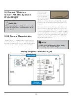
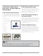
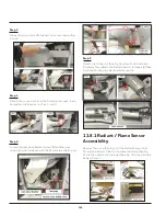
10.4 Radiant / Flame Sensor
10.4.1 General Characteristics
Flame sensor is a device that detects the
presence of a flame due to
combustion. It detects the
flame by detecting
electromagnetic
radiation, ionization, or
heat. When the dryer
operates on gas, it
requires an igniter to light
the gas and create a flame
to heat the air that is used
to dry the clothes. It also
requires a flame sensor to ensure that the flame continues
to burn inside the flame chamber. When the dryer does
not creates enough heat to dry your clothes, or if it does
not ignite a flame, you should test the flame sensor. A faulty
flame sensor will not allow the dryer to ignite and must be
replaced.
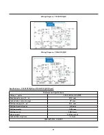
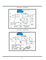
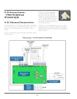
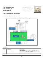
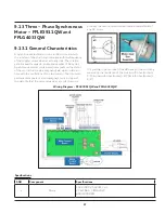
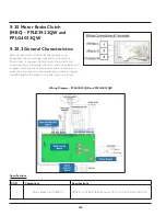
Wiring Diagram - FFLG4033QW
WARNING
When replacing the igniter, refer to the code shown
on the list of spare parts related to the appliance.
WARNING
When replacing the Radiant/Flame sensor, refer to
the code shown on the list of spare parts related to
the appliance.
Summary of Contents for FFLE3911QW
Page 1: ...Publication 5995666392 October 2015 Technical Service Manual Laundry Center ...
Page 2: ...I ...
Page 9: ...8 3 Product Features ...
Page 14: ...13 5 1 FFLE3911QW 5 1 1 Upper Cabinet Drum Heater 5 Exploded View and List of Parts ...
Page 17: ...16 5 1 2 Motor Blower Belt ...
Page 19: ...18 5 1 3 Control Panel ...
Page 21: ...20 5 2 FFLG4033QW 5 2 1 Upper Cabinet Drum Heater ...
Page 24: ...23 5 2 2 Motor Blower Belt ...
Page 27: ...26 5 2 3 Control Panel ...
Page 32: ...31 5 3 3 Wash Assembly POS NO DESCRIPTION 14 Screw 2 PLCS 15 Lock Hub Functional parts ...
Page 33: ...32 5 3 4 Cabinet Assembly ...
Page 69: ...68 User Interface of Laundry Center FFLG4033QW ...
Page 76: ...75 8 6 Wiring Diagram FFLE3911QW Electric Dryer Model ...
Page 77: ...76 8 7 Wiring Diagram FFLG4033QW Gas Dryer Model ...
Page 78: ...77 8 8 Wiring Diagram FFLE3911QW and FFLG4033QW Washer Model ...
Page 91: ...90 Wiring Diagram FFLE3911QW Wiring Diagram FFLG4033QW ...
Page 125: ...124 ...
Page 161: ...160 ...
Page 165: ...164 ...
Page 168: ...167 ...
Page 170: ...169 ...
Page 179: ...178 ...
Page 181: ...180 ...
Page 183: ...182 ...