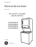


GE Appliances
General Electric Company
Louisville, Kentucky 40225
31-9208
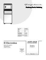
GTUP270EMWW
GTUP270GMWW
GTUP240EMWW
GTUP240GMWW
Technical Service Guide
March 2011
GE Appliances
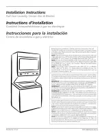
24- and 27-in. Unitized
Laundry Centers
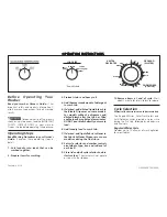
EASY CARE
COTTONS
COTTONS
DELICATES
PERMANENT PRESSS
DELICATES
S
WASHER | DRYER
TIMED DRY
DRYER
TEMPERATURES
LOAD SIZE
WASHER
TART
Summary of Contents for Spacemaker GTUP270EMWW
Page 15: ...15 Airflow...