


152
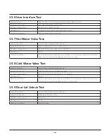
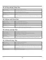
15.10 Three Water Valves Test
Selector position
Turn 4 clicks clockwise from the top
Purpose of the test
To test both hot and cold and, if present, the softener water valves and the softener
siphon drains fully, agitate function
Activated components
Door lock, three water valves, main motor
UI behaviour
None
Working conditions
Door locked, Add while water level lower than 55mm, for max. 5 minutes. The clutch
moves to the agitate position, if it was in spin. Agitate begins when the water level is
reached
15.11 Drain and Clutch Test
Selector position
Turn 5 clicks clockwise from the top
Purpose of the test
Drain system with the clutch mechanism
Activated components
Door lock, drain pump, clutch actuator
UI behaviour
None
Working conditions
Door locked, drum stop, run clutch to spin mode and drain until empty +10 seconds
more. Run clutch actuator for about 100 seconds
15.12 Drain and Spin Test
Selector position
Turn 6 clicks clockwise from the top
Purpose of the test
Verify drain system, and Pressure Sensor calibration procedure
Activated components
Door lock, main motor, drain pump
UI behaviour
None
Working conditions
Door locked, empty tub water level <5mm, if not the drain will run, if not in spin
mode the clutch actuator will run to spin position, spin up to maximum speed
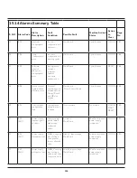
15.13 Alarm History Test
Selector position
Turn 7 clicks clockwise from the top
Purpose of the test
Communicate alarm history
Activated components
Buzzer
UI behaviour
A series of beeps separated by a short pause for one character and a long pause to
move to the second character. Press selector for next stored alarm. Example, count
12 beeps is a C
Working conditions
Drum stopped, Door unlocked
Summary of Contents for FFLE3911QW
Page 1: ...Publication 5995666392 October 2015 Technical Service Manual Laundry Center ...
Page 2: ...I ...
Page 9: ...8 3 Product Features ...
Page 14: ...13 5 1 FFLE3911QW 5 1 1 Upper Cabinet Drum Heater 5 Exploded View and List of Parts ...
Page 17: ...16 5 1 2 Motor Blower Belt ...
Page 19: ...18 5 1 3 Control Panel ...
Page 21: ...20 5 2 FFLG4033QW 5 2 1 Upper Cabinet Drum Heater ...
Page 24: ...23 5 2 2 Motor Blower Belt ...
Page 27: ...26 5 2 3 Control Panel ...
Page 32: ...31 5 3 3 Wash Assembly POS NO DESCRIPTION 14 Screw 2 PLCS 15 Lock Hub Functional parts ...
Page 33: ...32 5 3 4 Cabinet Assembly ...
Page 69: ...68 User Interface of Laundry Center FFLG4033QW ...
Page 76: ...75 8 6 Wiring Diagram FFLE3911QW Electric Dryer Model ...
Page 77: ...76 8 7 Wiring Diagram FFLG4033QW Gas Dryer Model ...
Page 78: ...77 8 8 Wiring Diagram FFLE3911QW and FFLG4033QW Washer Model ...
Page 91: ...90 Wiring Diagram FFLE3911QW Wiring Diagram FFLG4033QW ...
Page 125: ...124 ...
Page 161: ...160 ...
Page 165: ...164 ...
Page 168: ...167 ...
Page 170: ...169 ...
Page 179: ...178 ...
Page 181: ...180 ...
Page 183: ...182 ...