Installing and Removing Option Boards
Option Board Configurations
ModuSys 2000 Kernel
5-3
Option Board Configurations
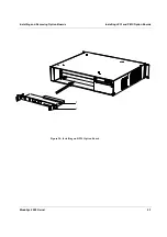
This section provides information on option board configurations. The
module unit has 8 external openings that can accommodate option boards.
One of these openings is reserved for the SBC, the remainder can be used by
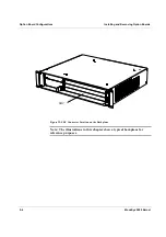
a mixture of cPCI options (refer to Figure 22). Consult the manuals for the
SBC for any additional requirements concerning power, adequate airflow
provision, and any other matters. You can install various combinations of
cPCI option boards onto the Force Computers ModuSys Product Family
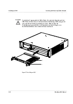
backplane (1). Installation of the SBC can only be made in the SBC
connectors (B) located on the backplane (refer to Chapter 2).
Note:
•
The blanking panels of the enclosure have a series of gaskets that
must connect with the gaskets of options cards. Take care when
inserting the option cards so that they connect with these gaskets. If
the option cards do not make proper contact with the gaskets,
unacceptable electromagnetic interference may be caused. Care must
also be taken when removing or installing the option cards.
Summary of Contents for MODUSYS 2000 Kernel
Page 5: ......
Page 9: ......
Page 11: ......
Page 13: ......
Page 17: ......
Page 21: ......
Page 25: ......
Page 26: ...1 Introduction...
Page 27: ......
Page 50: ...2 Backplane...
Page 51: ......
Page 64: ...3 Accessing Internal Components...
Page 65: ......
Page 71: ......
Page 72: ...4 Installing and Removing Storage Devices...
Page 73: ......
Page 84: ...5 Installing and Removing Option Boards...
Page 85: ......
Page 98: ...6 Replacing Module Unit Components...
Page 99: ......
Page 108: ...Replacing Module Unit Components Replacing the Power Supply Unit ModuSys 2000 Kernel 6 11...
Page 109: ......
Page 110: ...A Assembly Drawings...
Page 111: ......
Page 112: ...Assembly Drawings ModuSys 2000 Kernel A 3...

