ModuSys 2735 Connectors
Backplane
2-12
ModuSys 2000 Kernel
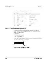
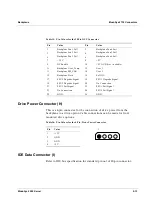
Table 14: Pin Values for the 20-Pin OCP Connector
Pin Value
Pin Value
1
Backplane Fan 1 Fail
2
Backplane Fan 4 Fail
3
Backplane Fan 2 Fail
4
Backplane Fan 5 Fail
5
Backplane Fan 3 Fail
6
Backplane Fan 6 Fail
7
+3.3 V
8
+5 V
9
GND
10
+5V AUX (Not Available)
11
Backplane Over_Temp
12
User 1
13
Backplane SM_CLK
14
User 2
15
Backplane Data
16
PSU Degrade Signal
17
DC Enable
18
Soft ON
19 GND
20 GND
20-Pin Server Management Connector (G)
The 26-pin OCP connector allows a single connection to be made to a
purpose-designed Server Management Board. This connection includes
signals from the following:
•
Fan Status
•
Individual Power Status
•
Over Temp signals
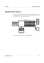
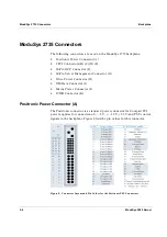
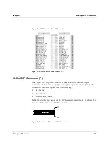
Table 14 lists the pin values for the OCP connector and Figure 14 shows the
location of the pins on the OCP connector.
P1
P2
Figure 15: Location of Pins on the OCP Connector
Summary of Contents for MODUSYS 2000 Kernel
Page 5: ......
Page 9: ......
Page 11: ......
Page 13: ......
Page 17: ......
Page 21: ......
Page 25: ......
Page 26: ...1 Introduction...
Page 27: ......
Page 50: ...2 Backplane...
Page 51: ......
Page 64: ...3 Accessing Internal Components...
Page 65: ......
Page 71: ......
Page 72: ...4 Installing and Removing Storage Devices...
Page 73: ......
Page 84: ...5 Installing and Removing Option Boards...
Page 85: ......
Page 98: ...6 Replacing Module Unit Components...
Page 99: ......
Page 108: ...Replacing Module Unit Components Replacing the Power Supply Unit ModuSys 2000 Kernel 6 11...
Page 109: ......
Page 110: ...A Assembly Drawings...
Page 111: ......
Page 112: ...Assembly Drawings ModuSys 2000 Kernel A 3...

