Cable Routing to the Front Access Drive Bay
Installing and Removing Storage Devices
4-12
ModuSys 2000 Kernel
Cable Routing to the Front Access Drive Bay
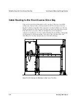
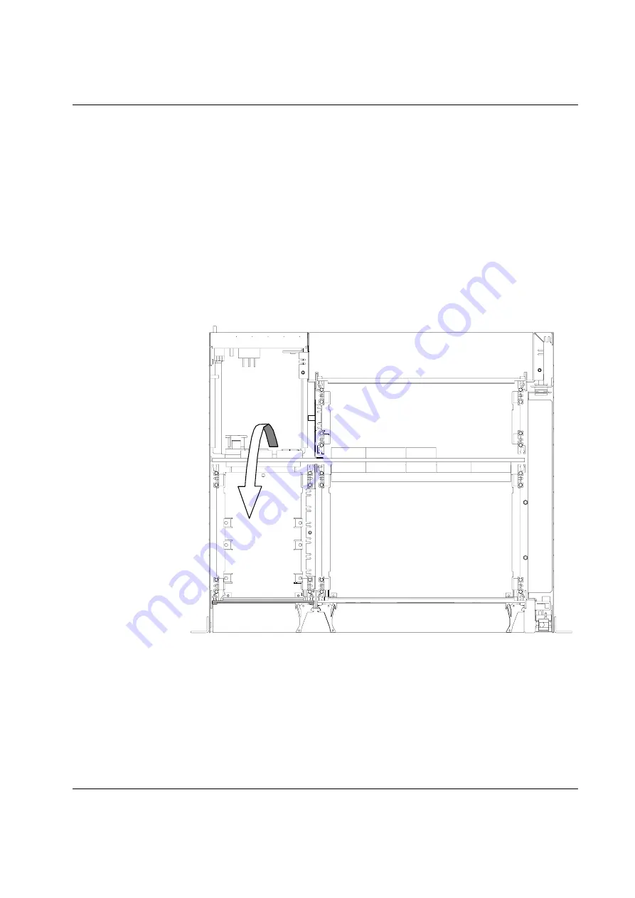
This section provides information on the routing of the power and IDE
cables to an internal drive, when mounted in the front access drive bay.
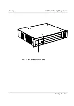
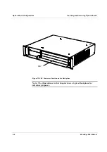
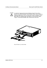
Figure 21 shows a diagram of the suggested routing of cables over the top
of the backplane for front mounted storage devices in the ModuSys kernel.
This cable route provides efficient routing between the backplane
connectors and the device drive and minimizing the possibility of trapping
or damaging the cable assemblies. Take care when routing cables and
installing or removing components to avoid cable damage.
Figure 21: Cable Routing over Backplane to Front Access Drive Bay
Summary of Contents for MODUSYS 2000 Kernel
Page 5: ......
Page 9: ......
Page 11: ......
Page 13: ......
Page 17: ......
Page 21: ......
Page 25: ......
Page 26: ...1 Introduction...
Page 27: ......
Page 50: ...2 Backplane...
Page 51: ......
Page 64: ...3 Accessing Internal Components...
Page 65: ......
Page 71: ......
Page 72: ...4 Installing and Removing Storage Devices...
Page 73: ......
Page 84: ...5 Installing and Removing Option Boards...
Page 85: ......
Page 98: ...6 Replacing Module Unit Components...
Page 99: ......
Page 108: ...Replacing Module Unit Components Replacing the Power Supply Unit ModuSys 2000 Kernel 6 11...
Page 109: ......
Page 110: ...A Assembly Drawings...
Page 111: ......
Page 112: ...Assembly Drawings ModuSys 2000 Kernel A 3...

