Backplane
ModuSys 2735 Connectors
ModuSys 2000 Kernel
2-7
CPCI Connectors (B) (C) (D) (E)
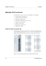
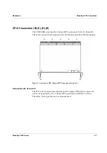
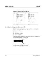
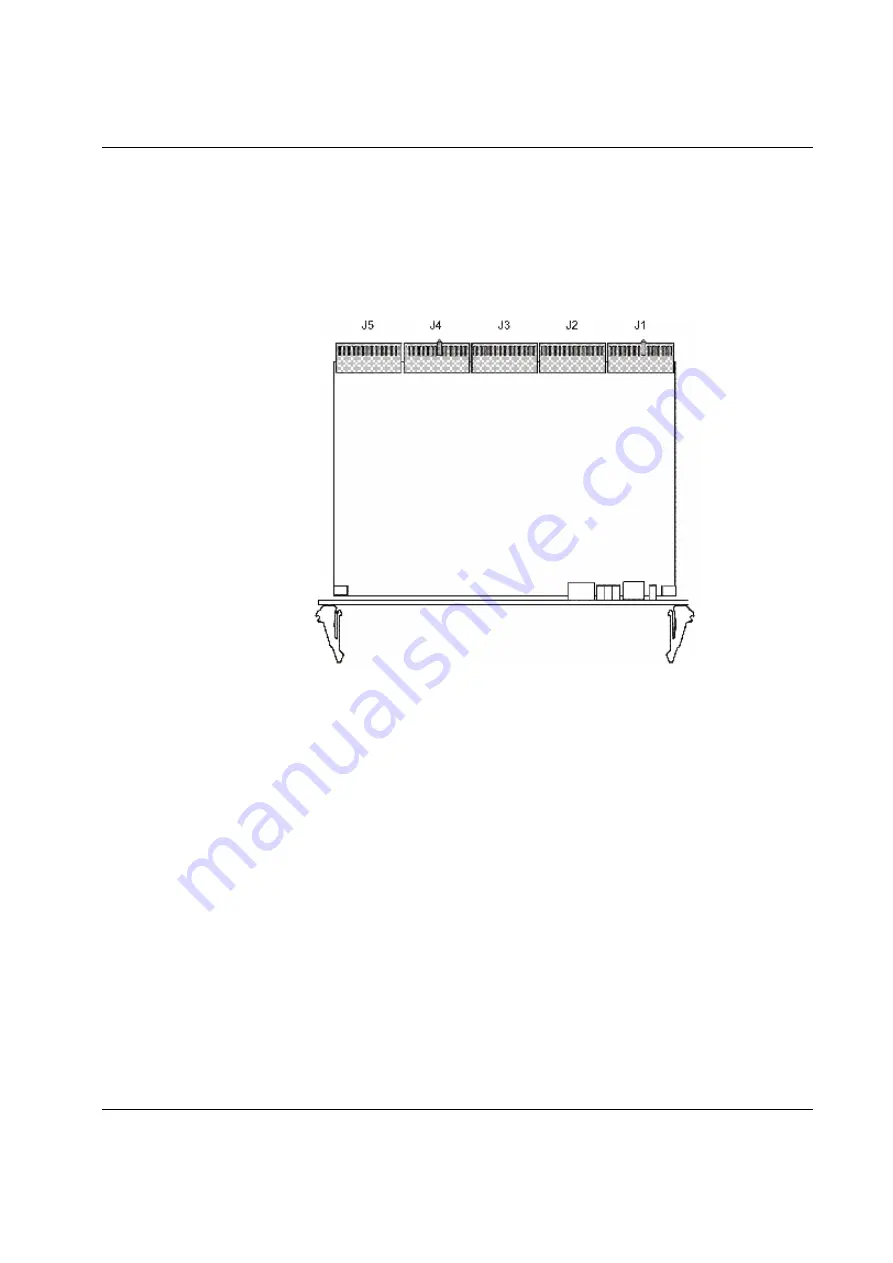
The 735R2 SBC provides the CompactPCI connectors J1, J2, J3, J4 and J5.
These correspond with signals on the cPCI connectors B on the backplane.
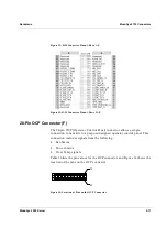
Figure 9: Location of SBC CompactPCI Connectors (Top View)
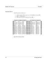
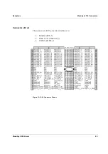
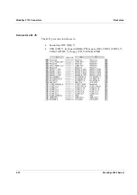
Connectors B; J1 and J2
The B; J1 and J2 connectors implement the CompactPCI 64-bit connector
pinout as specified by the CompactPCI specification PICMG 2.0 R3.0.
Therefore, these pinouts are not documented.
Summary of Contents for MODUSYS 2000 Kernel
Page 5: ......
Page 9: ......
Page 11: ......
Page 13: ......
Page 17: ......
Page 21: ......
Page 25: ......
Page 26: ...1 Introduction...
Page 27: ......
Page 50: ...2 Backplane...
Page 51: ......
Page 64: ...3 Accessing Internal Components...
Page 65: ......
Page 71: ......
Page 72: ...4 Installing and Removing Storage Devices...
Page 73: ......
Page 84: ...5 Installing and Removing Option Boards...
Page 85: ......
Page 98: ...6 Replacing Module Unit Components...
Page 99: ......
Page 108: ...Replacing Module Unit Components Replacing the Power Supply Unit ModuSys 2000 Kernel 6 11...
Page 109: ......
Page 110: ...A Assembly Drawings...
Page 111: ......
Page 112: ...Assembly Drawings ModuSys 2000 Kernel A 3...

