Introduction
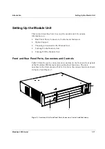
Setting Up the Module Unit
ModuSys 2000 Kernel
1-19
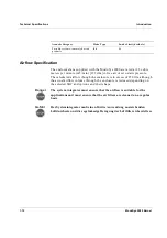
Danger
Use the Halt/Reset button only as allowed by the operating system.
Gefahr
Benutzen Sie den Halt/Reset Knopf nur so, wie es das Betriebssystem
erlaubt.
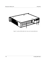
Table 10: Rear Panel Ports, Connectors and Controls for ModuSys Kernel
Item
Control or Indicator
Function
1
Power Supply Drive Bays
Available for additional removable power
supplies
2
Option slots
Depending on the options installed, these
slots may contain various ports, connectors,
controls or indicators. See your option
documentation for more information.
3 Display
Panel
Displays status of system and
configuration setting switches for the
system interface board.
4
Mains power input
connector
Enables one to connect the module unit to a
mains power socket. Requires cord with
IEC320-C13 connector.
5
Mains power switch
Switches the PSU ON or OFF.
Summary of Contents for MODUSYS 2000 Kernel
Page 5: ......
Page 9: ......
Page 11: ......
Page 13: ......
Page 17: ......
Page 21: ......
Page 25: ......
Page 26: ...1 Introduction...
Page 27: ......
Page 50: ...2 Backplane...
Page 51: ......
Page 64: ...3 Accessing Internal Components...
Page 65: ......
Page 71: ......
Page 72: ...4 Installing and Removing Storage Devices...
Page 73: ......
Page 84: ...5 Installing and Removing Option Boards...
Page 85: ......
Page 98: ...6 Replacing Module Unit Components...
Page 99: ......
Page 108: ...Replacing Module Unit Components Replacing the Power Supply Unit ModuSys 2000 Kernel 6 11...
Page 109: ......
Page 110: ...A Assembly Drawings...
Page 111: ......
Page 112: ...Assembly Drawings ModuSys 2000 Kernel A 3...

