Backplane
Connector Summary
ModuSys 2000 Kernel
2-5
Connector Summary
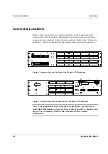
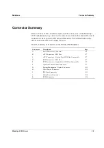
Refer to Table 13 for a brief description of the connectors on the ModuSys
2735 backplane and a pointer to the relevant section in this manual for each
connector where you can find more information. For information on the
cPCI connectors refer to Compact PCI spec.
Table 13: Summary of Connectors on the ModuSys 2735 Backplane
Connector Description
Page
A
Positronic Power Connector
2-6
B
cPCI Connectors –
SBC
Slot 2-7
C
cPCI Connectors – Option Slots H110 Bus Compatible
2-7
D
RTB Connectors – SBC Slot
2-7
E
RTB Connectors – Option Slots H110 Bus Compatible
2-7
F
Operator Control Panel Connector
2-7
G
System Management Option Connector
2-11
H
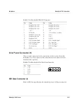
Drive Power Connector
2-12
I
IDE Data Connector
2-13
J
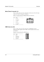
Mains Power Connector
2-14
K
ICMB Connector
2-14
Summary of Contents for MODUSYS 2000 Kernel
Page 5: ......
Page 9: ......
Page 11: ......
Page 13: ......
Page 17: ......
Page 21: ......
Page 25: ......
Page 26: ...1 Introduction...
Page 27: ......
Page 50: ...2 Backplane...
Page 51: ......
Page 64: ...3 Accessing Internal Components...
Page 65: ......
Page 71: ......
Page 72: ...4 Installing and Removing Storage Devices...
Page 73: ......
Page 84: ...5 Installing and Removing Option Boards...
Page 85: ......
Page 98: ...6 Replacing Module Unit Components...
Page 99: ......
Page 108: ...Replacing Module Unit Components Replacing the Power Supply Unit ModuSys 2000 Kernel 6 11...
Page 109: ......
Page 110: ...A Assembly Drawings...
Page 111: ......
Page 112: ...Assembly Drawings ModuSys 2000 Kernel A 3...

