Introduction
Setting Up the Module Unit
ModuSys 2000 Kernel
1-21
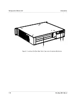
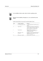
Table 11: Operator Control Panel Indicators
Item Control
or
Indicator Function
1
PWR
Power ON/OFF status LED
Indicates the status of the output/input
of the PSU.
2
DEG
Degrade indicator
Power supply over temperature
warning signal.
3
FAN
Fan failure indicator
Indicates when a fan stops working.
4
TEMP
Over
temperature
indicator Indicates that the temperature in the
module unit has reached a critical level
(approximately 60°C).
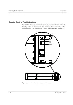
The item numbers in the first column of Table 11 refer to the various
functions shown in Figure 4.
Option Support
For more information about the options supported by the SBC you choose,
consult the SBC user documentation or contact your SBC supplier.
Choosing a Location for the Module Unit
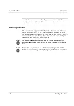
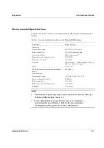
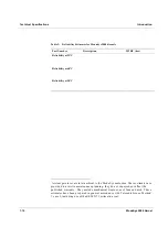
Choose a location for the ModuSys 2000 enclosure that complies with the
environmental specifications listed in Table 8. You must leave a minimum
clearance of 3 inches at the front and rear of the module unit to allow air to
circulate. Air vents on the top, front, side, and rear of the module unit must
be left clear to allow adequate air circulation to prevent excessive heat,
which can damage the internal components. Table 12 lists the various
locations where you must not operate the module unit.
Caution
!
If the module unit is mounted on a rack, then the system integrator is
responsible for the mechanical stability of the rack configuration in both
of the following situations:
•
When the module unit is in the fully home position
•
When the module unit is in the fully extended position
The system integrator is also responsible for the thermal design in the
enclosure.
Summary of Contents for MODUSYS 2000 Kernel
Page 5: ......
Page 9: ......
Page 11: ......
Page 13: ......
Page 17: ......
Page 21: ......
Page 25: ......
Page 26: ...1 Introduction...
Page 27: ......
Page 50: ...2 Backplane...
Page 51: ......
Page 64: ...3 Accessing Internal Components...
Page 65: ......
Page 71: ......
Page 72: ...4 Installing and Removing Storage Devices...
Page 73: ......
Page 84: ...5 Installing and Removing Option Boards...
Page 85: ......
Page 98: ...6 Replacing Module Unit Components...
Page 99: ......
Page 108: ...Replacing Module Unit Components Replacing the Power Supply Unit ModuSys 2000 Kernel 6 11...
Page 109: ......
Page 110: ...A Assembly Drawings...
Page 111: ......
Page 112: ...Assembly Drawings ModuSys 2000 Kernel A 3...

