ModuSys 2000 Kernel
xiii
Using This Manual
This manual introduces the ModuSys 2000 Kernel and describes the Force
Computers ModuSys Product Family 2U enclosure. It contains information
on the product features, using storage devices, installing or removing
option boards and module unit components.
This manual is for authorized personnel, including field service engineers
responsible for building, configuring, and expanding systems created with
ModuSys family of Modular Computing Components. You must be familiar
with computer equipment and components before you use this manual.
You must also be familiar with assembling and disassembling computer
equipment.
Conventions
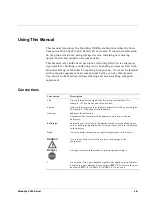
Convention Description
n.nn
A period in numerals signals the decimal point indicator. For
example, 1.75 equals one and three-fourths.
nn nnn
A space character separates digits in numerals with 5 or more digits.
For example, 10 000 equals ten thousand.
Italic type
Indicates the following:
Complete titles of associated documents and inline electronic
addresses
bold type
In procedures, (n) refers to the number in the corresponding figure.
In text, bold type highlights the first occurrence of a term referenced
in the glossary.
Note
A note contains information of special importance to the reader.
Caution
!
A caution contains information to prevent damage to the
equipment.
Danger
A danger contains information to prevent personal injury.
*
An asterisk (*) in a part number signifies any number in a particular
position in a part number. For example, EBM3*-PA refers to the part
numbers EBM31-PA, EBM32-PA, EBM33-PA, and so on.
Summary of Contents for MODUSYS 2000 Kernel
Page 5: ......
Page 9: ......
Page 11: ......
Page 13: ......
Page 17: ......
Page 21: ......
Page 25: ......
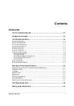
Page 26: ...1 Introduction...
Page 27: ......
Page 50: ...2 Backplane...
Page 51: ......
Page 64: ...3 Accessing Internal Components...
Page 65: ......
Page 71: ......
Page 72: ...4 Installing and Removing Storage Devices...
Page 73: ......
Page 84: ...5 Installing and Removing Option Boards...
Page 85: ......
Page 98: ...6 Replacing Module Unit Components...
Page 99: ......
Page 108: ...Replacing Module Unit Components Replacing the Power Supply Unit ModuSys 2000 Kernel 6 11...
Page 109: ......
Page 110: ...A Assembly Drawings...
Page 111: ......
Page 112: ...Assembly Drawings ModuSys 2000 Kernel A 3...


