Connector Locations
Backplane
2-4
ModuSys 2000 Kernel
A
A
B
C
C
C
E
D
F
G
H
I
J
K
H
I
E
E
Connector Locations
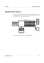
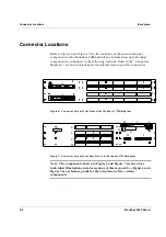
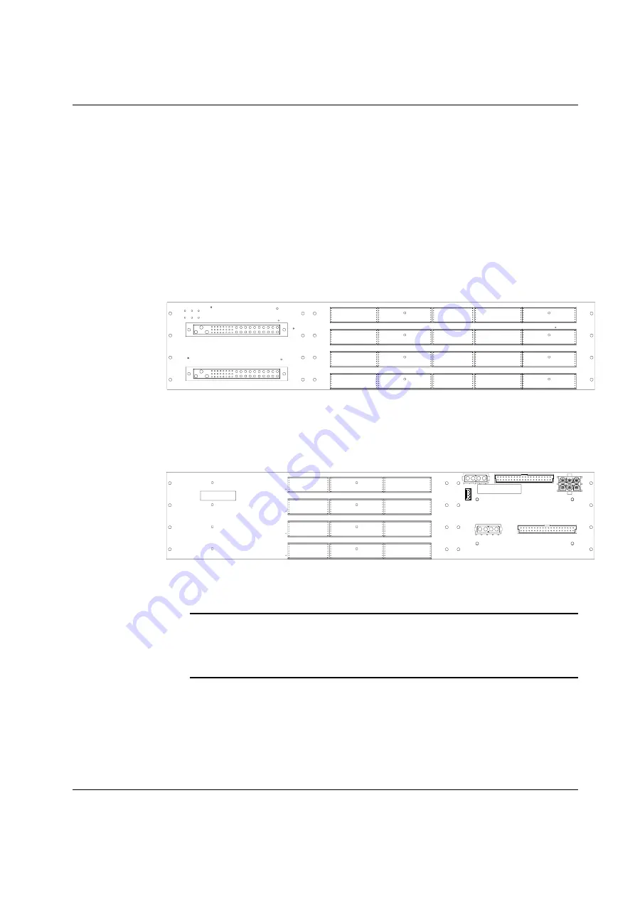
Refer to Figure 6 and Figure 7, for the locations of the main functional
components of the ModuSys 2000 backplanes. Information on individual
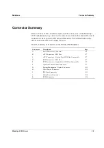
components is contained in the following sections. Refer to the “Connector
Summary” section in this chapter for information on specific connectors.
Figure 6: Connector Layout of the Front of the ModuSys 2735 Backplane
Figure 7: Connector Layout of the Rear Side of the ModuSys 2735 Backplane
Note: The components shown in Figure 6 and Figure 7 are shown as
individual illustrations in later sections of this manual. Use Figure 6 and
Figure 7 as a reference guide for the orientation of the various
components.
Summary of Contents for MODUSYS 2000 Kernel
Page 5: ......
Page 9: ......
Page 11: ......
Page 13: ......
Page 17: ......
Page 21: ......
Page 25: ......
Page 26: ...1 Introduction...
Page 27: ......
Page 50: ...2 Backplane...
Page 51: ......
Page 64: ...3 Accessing Internal Components...
Page 65: ......
Page 71: ......
Page 72: ...4 Installing and Removing Storage Devices...
Page 73: ......
Page 84: ...5 Installing and Removing Option Boards...
Page 85: ......
Page 98: ...6 Replacing Module Unit Components...
Page 99: ......
Page 108: ...Replacing Module Unit Components Replacing the Power Supply Unit ModuSys 2000 Kernel 6 11...
Page 109: ......
Page 110: ...A Assembly Drawings...
Page 111: ......
Page 112: ...Assembly Drawings ModuSys 2000 Kernel A 3...

