97
2121331-04-04/19 (Translation of the original operating instructions)
Operating Instructions
Modular Safety Control System MSC
EN
9.2.2.6. Optoelectronic safety light grid or safety laser scanner (ESPE)
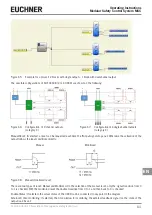
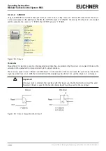
Using the ESPE function block the input status of an optoelectronic safety light grid (or safety light scanner) is checked. If
the area protected by the light curtain is interrupted (outputs on the light grid FALSE), the OUTPUT output is "0" (FALSE).
Conversely, if this area is clear and the outputs on the light curtain are "1" (TRUE), the OUTPUT output is "1" (TRUE).
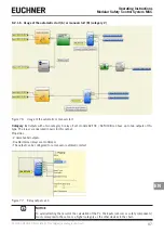
Figure 93: ESPE
Parameter
Manual Reset: If selected, a reset can be requested each time the area protected by the safety light grid is interrupted.
Otherwise the activation of the output will correspond directly to the input conditions.
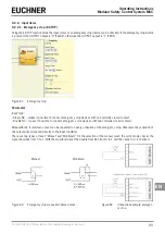
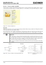
There are two types of reset: "Manual" and "Monitored". On the selection of the manual reset, the system only checks the
signal transition from 0 to 1. With the monitored reset the double transition from 0 to 1 and then back to 0 is checked.
Manual
Monitored
Figure 94: ESPE manual/monitored reset
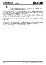
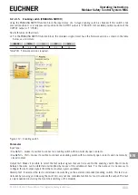
Figure 95: Connection example, ESPE
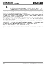
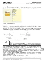
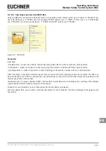
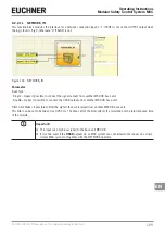
Important!
If manual reset is selected, the next input after the inputs used by the function block must be used.
Example: If Input1 and Input2 are used for the function block, Input3 must be used for the reset input.
The OUT TEST signals cannot be used for the static safety output ESPE, as the test signals are generated by the ESPE.
StartUp Test: If selected, the test is undertaken on switching on the safety light grid. This test is undertaken by occupying
and clearing the area protected by the safety light grid to carry out one complete function test and to activate the output.
This test is only requested on starting the machine (on switching on the module).
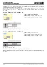
Filter (ms): Makes it possible to filter the signals received from the safety light grid. This filter can be set to between 3 and
250 ms and removes any contact bounce. The time set for the filter affects the calculation of the total response time of
the module.
With Simultaneity: If selected, the simultaneous switching of the signals received from the safety light grid is checked.
Simultaneity (ms): This control is only available if the previous parameter has been selected. Using this value you can define
the maximum permissible time (in ms) between the switching of the two different signals received from the safety light grid.
Summary of Contents for MSC
Page 1: ...EN Operating Instructions Installation and use Modular Safety Control System MSC ...
Page 171: ......
Page 173: ......

